First came the desktop. Then came the laptop. And the netbook. And the smartphone. There was talk of “convergence”. That somehow didn’t go well as planned.
With KiteBoard, we did plan for convergence. To that end, we kept the display connector reasonably generic – generic enough so that we could support a variety of actual displays by creating a new “display interface board”. The following possibilities can be supported with an appropriate interface board:
- A standard display + capacitive touch module (these are used in common smartphones)
- HDMI with audio output
- LVDS displays, with or without a touch panel
- RGB displays, with or without a touch panel
- DisplayPort
- VGA
That should pretty much cover all display technologies that one would want to reasonably use with Kite.
Kite’s display connector includes a bunch of MIPI DSI signals (4 data+1 clock– all of them differential pairs), PWM, I2C, I2S, a few GPIOs, and power. All these make it possible to connect KiteBoard to any display. Up until now, we have only shown the 5” phone display connected to the phone… with an intermediate display board. That worked well till now.
When I call Kite a “smartphone” kit, people start thinking in a restrictive manner. Fair enough – given the state of today’s smartphones. However, Kite is more like a “swiss army knife” of mobile computing. To demonstrate that, in this post, I show how you can connect the KitePhone to a HDMI display.
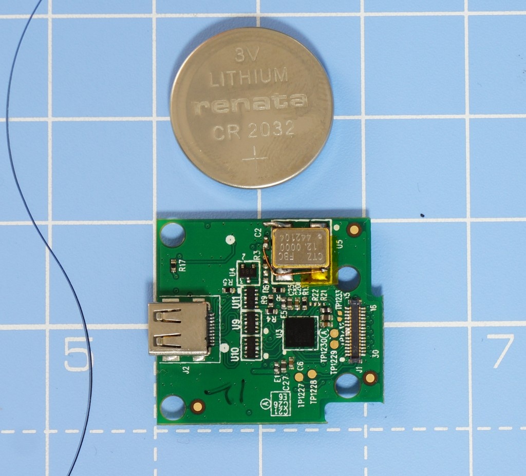
To make that happen, we have created a compact HDMI board, pictured below.
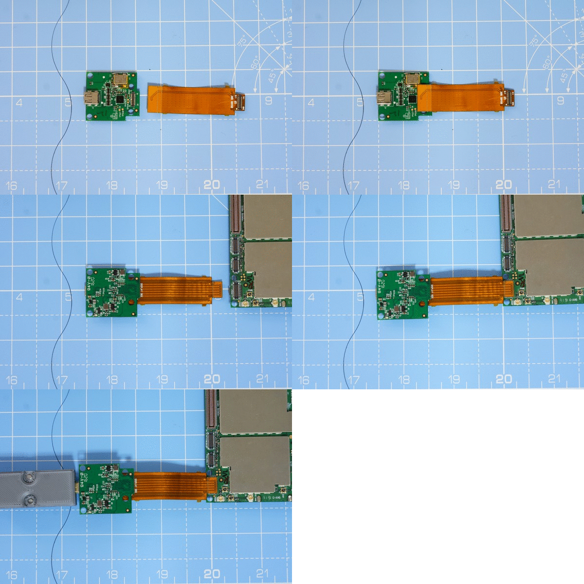
The display flex (that we used with the display board) is used to connect this to the KiteBoard. The below animation shows how this works.
The HDMI board converts the MIPI signals to HDMI using a “bridge” chip – ADV7535. This bridge chip takes audio input over the I2S lines, and renders the audio output over HDMI. The bridge chip is configured and controlled using I2C – through a kernel driver. Those interested in the hardware details of the HDMI board are requested to refer to the schematic.
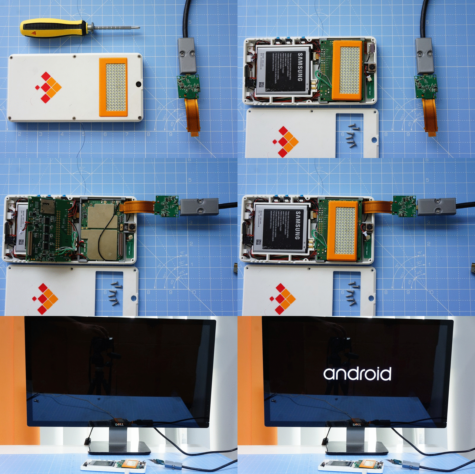
How do we make this work with the phone, though? The casing does not have any provision for HDMI, so we will have to open the phone. Using the screwdriver, we open the back cover of the phone. Then, gently disconnect the earpiece connector. Unplug the expansion board. The display connector is now accessible. Disconnect the display panel. Connect the HDMI board in place of the display panel. Connect the HDMI board to a HDMI monitor. Ensure that the monitor is powered on. Next, connect the expansion board back in its position. Turn ON the device by pressing the power button. Keep the Volume Up button pressed.
The vibration motor will announce that the device is powered on, but you won’t see anything on the display. and you will now be in the bootloader mode. After a few seconds, you will see images on the HDMI screen – the familiar “android” boot animation.
How did this work? If you are familiar with Android, you know that pressing the volume UP key while turning on the phone takes you to Android “recovery”. The “recovery” mode generally invokes a kernel & a set of userspace utilities which handle the recovery aspect. In my case, I replaced the recovery with a copy of my kernel boot image, with one difference: the recovery image is configured to use HDMI in place of the default 5” display panel. Due to this implementation, you do not not see the splash screen (the bootloader is responsible for the splash screen –it did not change – the HDMI monitor complains at this point about bad timing). As soon as the kernel boots and Android is up, you start seeing images on the HDMI monitor.
It's a simple three step process to configure recovery in this way. Use a USB cable to connect Kite to your laptop, and then punching some commands in that shell:
$ adb reboot bootloader
$ fastboot flash recovery boot-hdmi.img
$ fastboot reboot-recovery
The last command boots the device to recovery – i.e. with HDMI enabled, in this case.
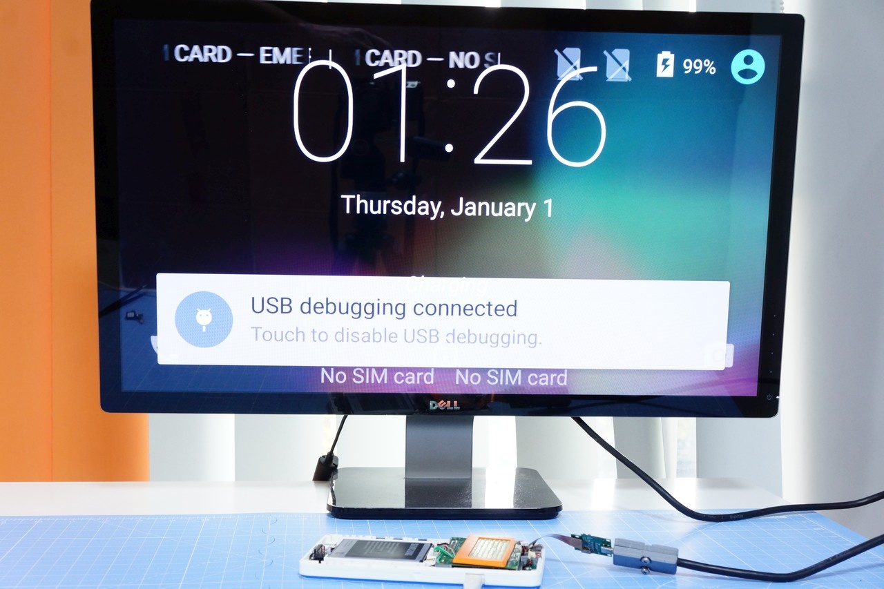
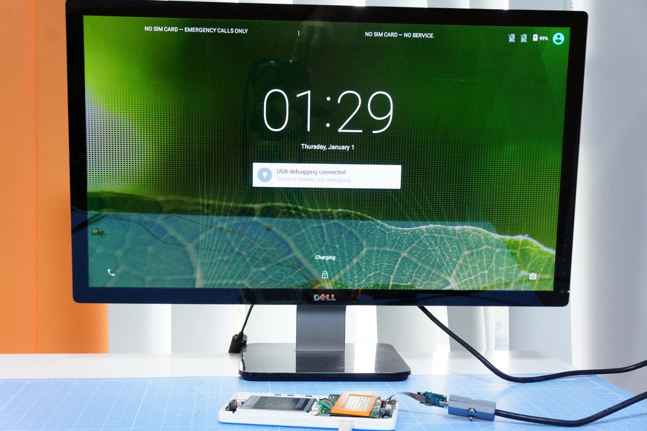
After the android boot animation, in a few seconds, we see the lock screen. Nice! But wait it’s all jumbled up.
Android still thinks that it’s a phone screen. Not to worry – it’s easy to fix using adb
$ adb shell wm density 160
$ adb reboot
After the device reboots, the desktop will now seem natural.
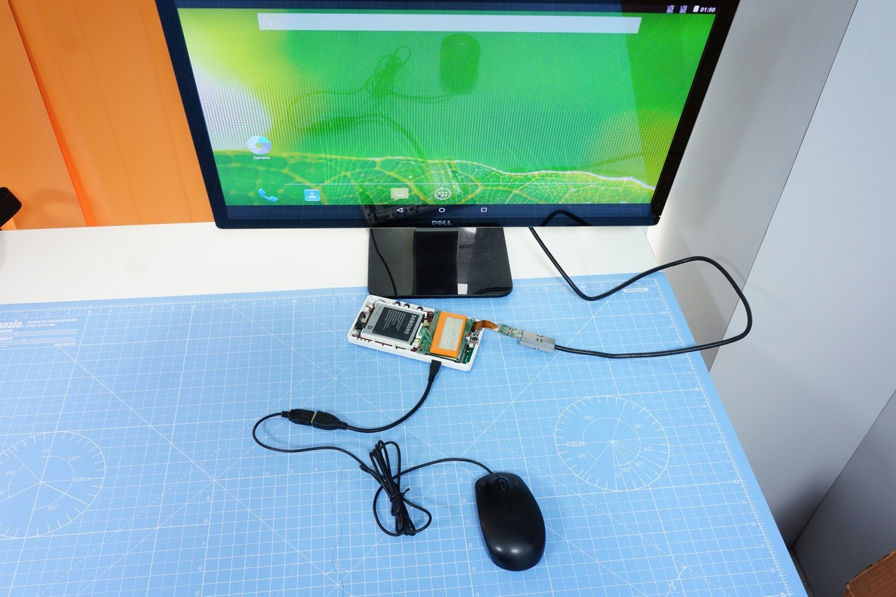
So, what do we do now? In a short while, the screen will turn off & go to sleep. If you press the power button, it will come back. There is no touch screen, so we need a mouse to interact with the screen.
KiteBoard has a single USB OTG port. You may connect the USB mouse to the OTG port & get started. Unlock the screen & move around in Android. The navigation bar is still on-screen, so you can use the “back” button from there. The camera works too. And the other things as well.
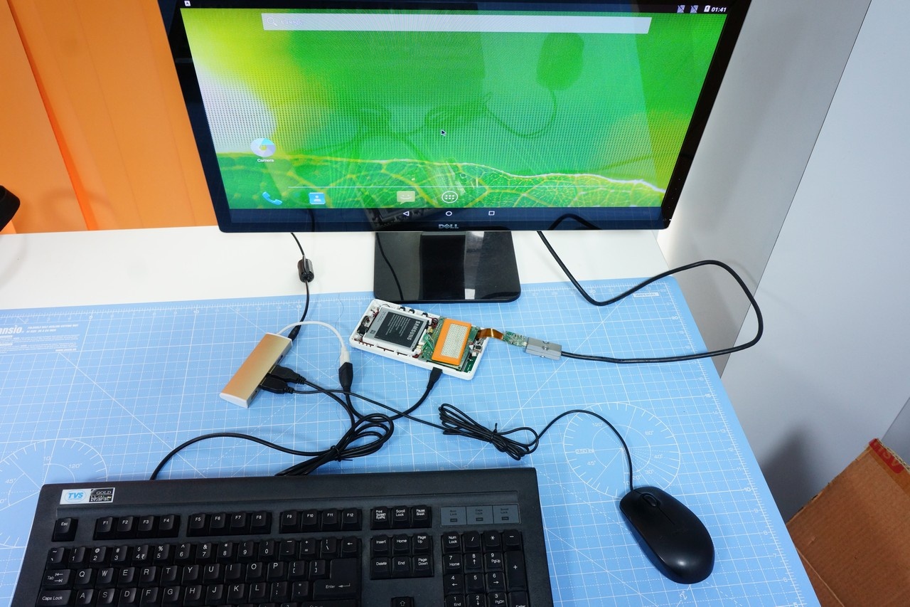
HDMI is all about productivity. That possibly means a keyboard too, right? Put that USB hub to good use. Use a keyboard & a mouse. You can now do some email in comfort, and maybe spreadsheets… You'll also find that the ESC button is equivalent to the BACK button in Android!
How about something more interesting? Like, say, programming that Arduino sitting on your desk? Yes, there are “apps” to do that. However, wouldn’t it be nice if would could just use the standard Arduino IDE on the device. KiteBoard can run a Debian chroot environment when needed, with SSH enabled. In the chroot environment, we could run an X server. The Arduino IDE can then be run inside that environment
To start the chroot environment, you could do
$adb root
$ adb shell start chroot
That will do this once – but won’t work across reboots. Or, you could edit /system/bin/hwsetup.sh. This is the hardware setup script that the KiteBoard runs at boot.
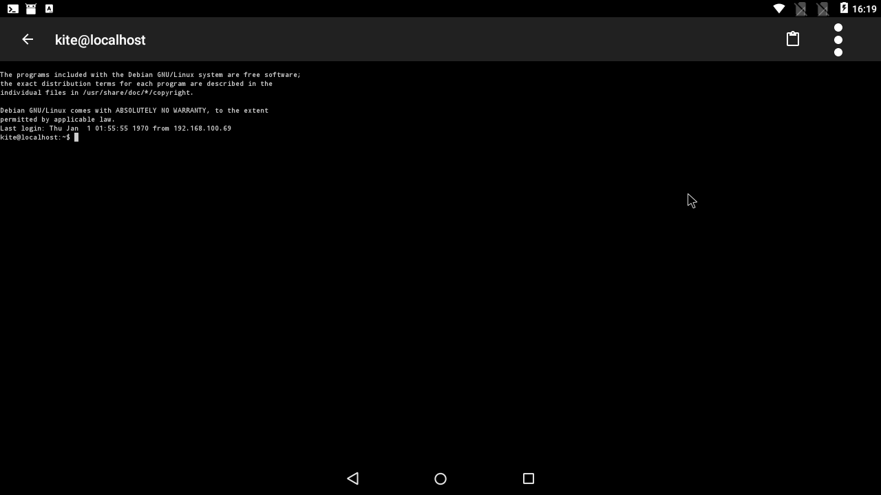
Let’s SSH into the chroot environment. The ConnectBot app is your friend. Host localhost, username kite, and password 123 will get you in. (Yeah, security risk, I know.)
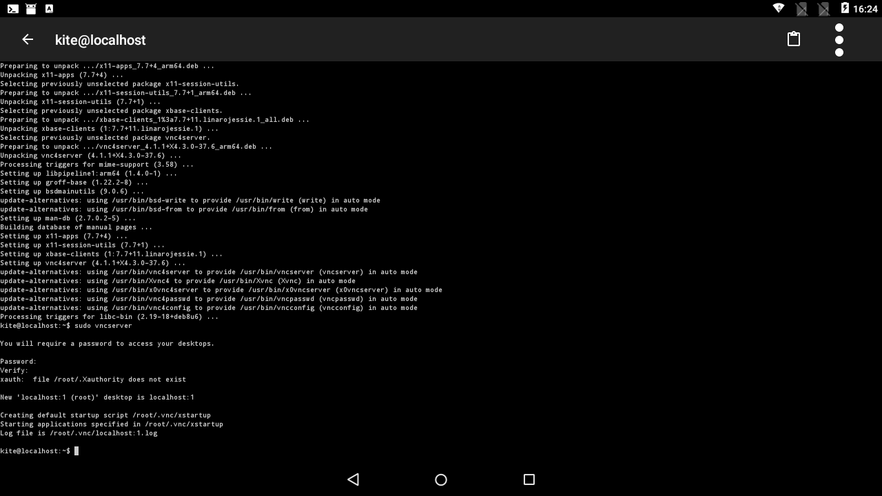
Once inside, we can start a VNC server.
$ sudo apt-get install vnc4server
$ sudo vncserver
The actual ConnectBot window looks like this:
Now, you can install the AndroidVNC client (It’s ancient, but it works) using FDroid. The server is localhost:5901, that’s all you need to know. After the VNC client connects, you may use the X desktop. The X environment can is functional, but can take a bit of getting used to. In any case, you can double click on the desktop & start a terminal. Inside the terminal, install the Arduino IDE.
$ sudo apt-get install Arduino
$ arduino
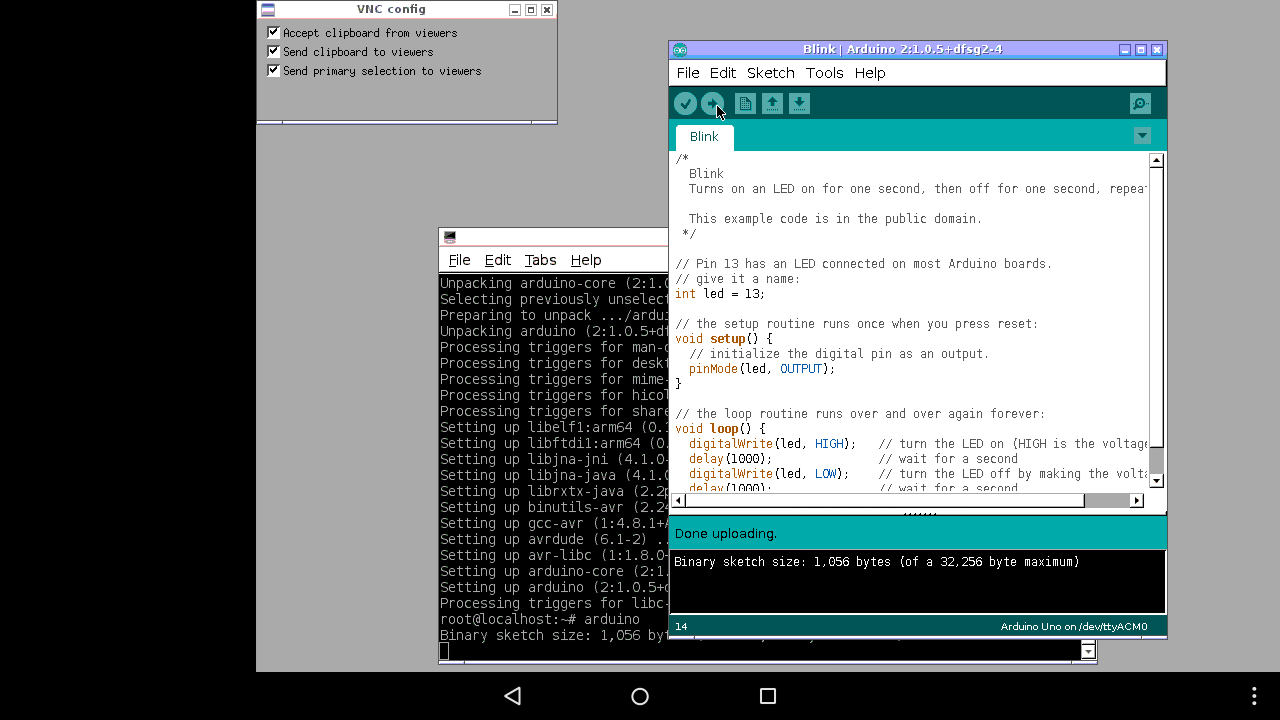
Connect the Arduino to the USB hub. The Arduino shows up as /dev/ttyACM0 . Load the sketch, like you always do:
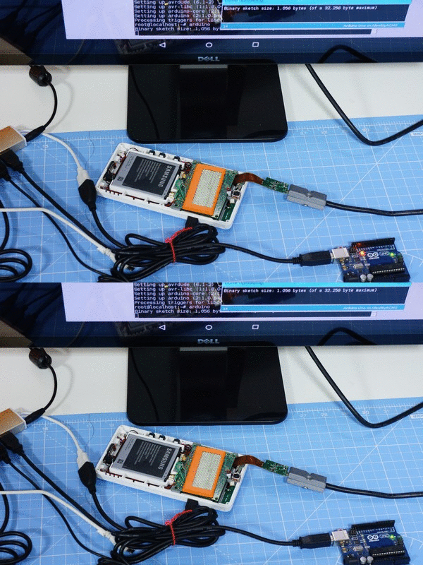
And blink that LED!
Excited already? But wait, we can make life a little more interesting. Wouldn’t it be cooler if you could just use an Arduino Pro Mini instead of that large Arduino? That would make good use of the Raspberry Pi compatibility on the expansion board.
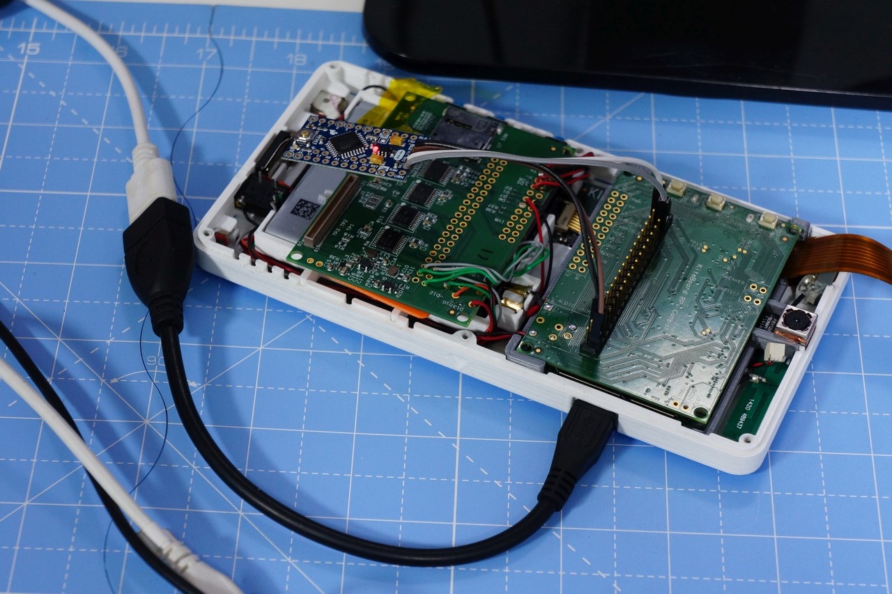
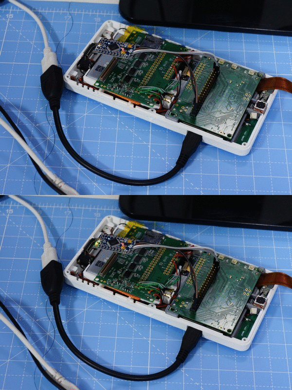
The expansion board has the 40 pin HAT compatible footprint. We could connect an Adafruit Pro Mini (3.3V version) to that connector, and power it with the 3.3V output. To make my life easier, I took an extra expansion board & soldered a 40 pin header on it. The expansion board has a provision for SMD standard buttons – which I have populated on this expansion board. At this point, I thought that I was ready to use the Arduino IDE to blink that LED on the 3.3V Arduino Pro Mini.
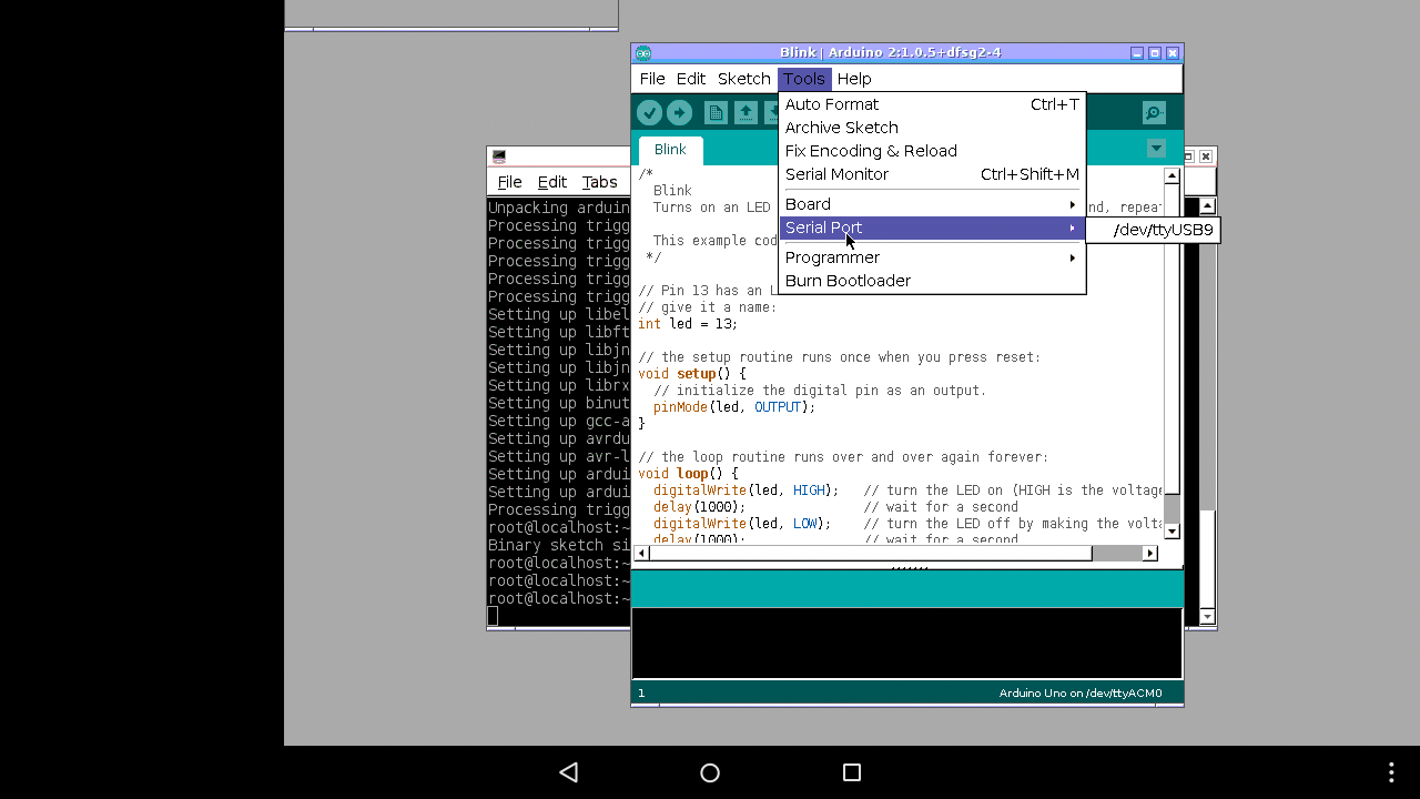
Not so fast. Turned out that Arduino just wouldn’t detect the serial port… There are two serial ports on KiteBoard – the system debug port (this can be disabled when required - /dev/ttyHSL0), and a second serial port /dev/ttyHS0. Both of them aren’t recognized/detected by the Arduino IDE. As always, google and stack exchange had the required workarounds.
I ended up adding the following line to hwsetup.sh to create workaround this problem – basically symlink /dev/ttyUSB9 to /dev/ttyHS0:
ln -s /dev/ttyHS0 /dev/ttyUSB9
Now, Arduino knows ttyUSaB9 !
After this change, I am able to program the Arduino Pro Mini from Arduino, running inside the chroot environment, accessible via VNC inside the Android desktop. And I am in control with my Keyboard & Mouse.
At this point, my phone is effectively my lab-in-the-pocket… Close to convergence? What do you think?
At this point, you are probably asking -- how do I get back to using the phone screen... Disconnect the HDMI, connect back the phone screen, close the cover & boot the phone as usual! Oh yeah, the UI will appear a bit jumbled; that can be fixed by changing the screen density to 320:
$ adb shell wm density 320
As you might guess, there are "apps" to do that as well !
As an ending note, let me say that the software isn’t in a “plug & play” state right now. In our current implementation, we have a functional HDMI display output that looks works like a “display panel”. In technical terms, the resolution is hard-coded in the kernel. In a complete HDMI implementation, the actual connected display must be queried, and EDID data must be used to setup the resolution. Apart from that, everything works...
The current KiteBoard has a single display connector - that results in a bit of ugliness. With KiteBoard v2, we will have two display connectors. Potentially, we could have both the HDMI and the "phone" screen active at the same time... or two HDMI displays powered by a single Kite v2. I eagerly await that day!


Leave a comment here