A KitePhone is simply a phone built using the Kite Kit. Consumer phones go through a teardown, so that folks can understand how they are built. Kite is built for makers, so we take a "build" approach here.
In this post, I will show you how we’ve put together a minimally complete model of a phone. We call this model, “Poorna”. Poorna is a Sanskrit word, commonly meaning “complete”. It can also mean “zero”, and there are philosophical interpretations too, but then I digress. Poorna is a complete phone providing functionality like the smartphone in your pocket. No additional bells & whistles, just pure Android.
Here is a short overview video (exactly 2 minutes, 17 seconds) of how to build Poorna, starting from Kite:
Still reading, and interested to learn more? The complete details are down below, in quite some detail. I need to warn you again: this post is long, and extremely detailed. It details the entire kit, some design decisions, throws some light into the mechanical design, and kit assembly. If I were you, I'd grab a cup of coffee (perhaps more), and then proceed!
The Kit
First, let’s start with Kite, the DIY modular smartphone kit. As the video above illustrates, this kit has everything you need to build a complete phone (Minimal tools, and some soldering is required, but nothing pro level.) Let’s briefly go over the items in the kit.
The KiteBoard is the “brains” of the kit. I find it useful to think of it as the motherboard of/for a phone. KiteBoard is based on the Qualcomm MSM8916.
KiteBoard has a sub credit card form factor (70 mm x 50 mm), with a low profile – around 5.5 mm including all connectors. KiteBoard includes a modem, a quad core 64 bit 1.2 GHz ARM Cortex A53 processor (with Adreno GPU), WiFi/BT, GPS, 16 GB of onboard storage (eMMC), 1 GB of RAM, integrated 9 axis accelerometer/gyroscope/magnetometer sensor, and a LiPoly battery charger. Various connectors on KiteBoard allow you to include custom hardware features required for your project. KiteBoard’s pins work at a voltage level of 1.8V. The complete specifications of KiteBoard are here.
The expansion board converts the I/O pins of the board to 3.3V logic level, making it accessible to makers. We believe that makers must be able to use common components available to them to create devices that solve specific needs. To that end, we have provided a 40 pin Raspberry Pi compatible connector. The expansion board also makes the audio portion of the board accessible to makers. The expansion board is the same size as the KiteBoard, and stacks right on top of it.
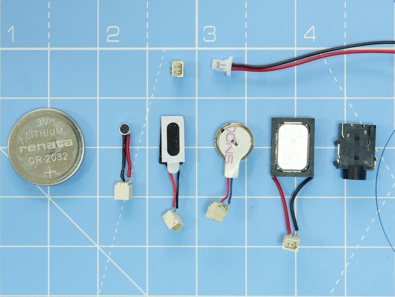
A tested speaker, microphone, earpiece, and a 3.5mm audio socket are included in the kit. We’ve carefully chosen small components here, which are still large enough to be usable. In the kit, these components are provided soldered to tiny connectors (these are 1mm pitch male shrouded headers). To get a fair idea of the size of these components, have a look at the picture below. The CR2032 battery is in the picture for a size comparison. The picture also shows 1mm pitch plug that is used to connect the audio components to the boards.
The 5 inch (diagonal) display module is one of the nicer parts of the kit, featuring 720p resolution, and an integrated 5 point capacitive touch panel. The display features excellent color reproduction. Plus, at 700 nits brightness – it’s brighter than most mid range phones that you are likely to come across... A display board and a couple of flex cables are used to the display module to KiteBoard.
The 8 MP camera module is capable of autofocus – which is crucial to its usage in a phone (or any handheld device, for that matter). We also have two flex cables in the kit that allow the camera module to be placed farther away from the board. The flex cables aren't shown in the picture, as they are not used in this build.
Kite includes separate antennas for WiFi/BT, GPS and LTE. The WiFi/BT and LTE antennas are available from DigiKey, and maybe other vendors.
Schematics of the boards & flex cables are in kite-design-v01.zip .
3D Printed Parts
To put Poorna together, the enclosure & internal board holders need to be 3D printed.
3D printing plays a major role in this project. The complete phone & everything required to hold the components in place is 3D printed. We have designed the models such that any common printer is sufficient to reproduce our results. That means minimum overhangs, 45 degree slopes and no tricky requirements for support material that is tough to cleaned up afterwards. The complete model files for Poorna have been uploaded to the site, as poorna-v01.zip .
There are 5 separate 3D printed pieces in the design: the front cover, the back cover, a board holder, a battery holder, and a small part to support the audio jack. The front cover & back cover together make up the overall enclosure – what you’d generally call the “phone”.
The printed parts are pictured here:
The board holder needs to be printed with supports enabled; I use the option “Support touching build plate” on Slic3r. The rest can be printed without any special settings. Generally, I use 0.2 mm layer heights and the other defaults (20% infill). And of course, PLA filament.
For the sake of completeness, I should mention that that the orange parts pictured in this example were printed with a fine (0.25 mm) nozzle. ColorFabb nGen Orange was used for the externally visible parts. The board holder and battery holder are printed with ColorFabb PLA.
I don’t quite remember exact print times. The board holder and the battery holder take around 30-45 mins each at default speeds on my Prusa i3 MK2 Multimaterial printer – and printed with a single fiilament. The orange parts were printed with the fine nozzle, and ended up taking around 12 hours. With a 0.4mm nozzle, print times must be under six hours.
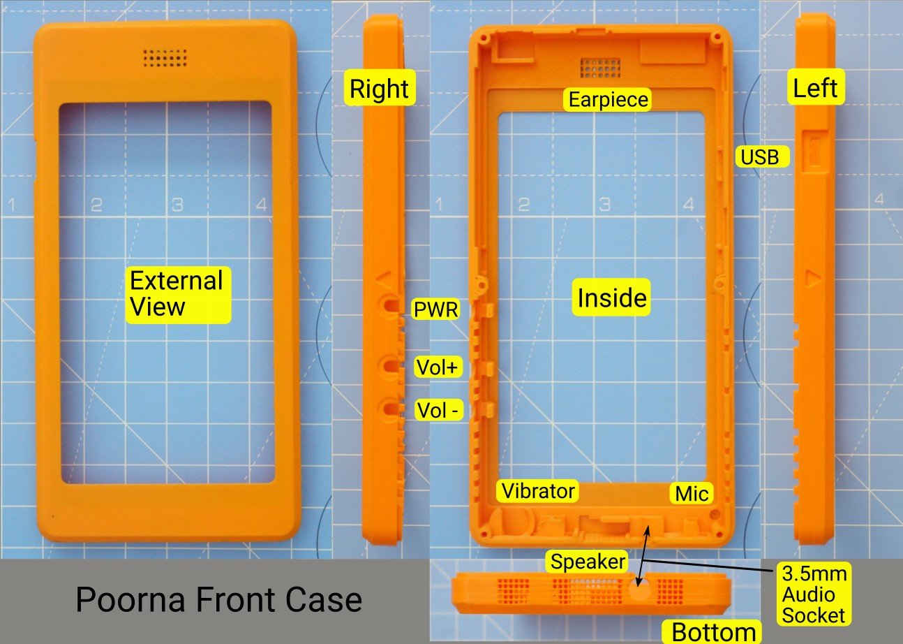
Let’s look at the design itself a bit. Important aspects of the front cover are labelled here:
Note the slots in the front cover for the display module, 3 push buttons, a vibrator, speaker, microphone and earpiece, and a 3.5 mm audio socket.
Why did we use standard push buttons? Because we can! Also, we wanted to keep away from specialized components (like dome switches, more PCBs, and so on), as much as we could.
The front face shows the earpiece grille. There is an oh-so-tiny hole for the microphone. The speaker is positioned at the center of the device, below the screen. There is a speaker grille in the front cover. The left and right parts of grille are faux – designer touches.
A hole for the USB connector is by the side.
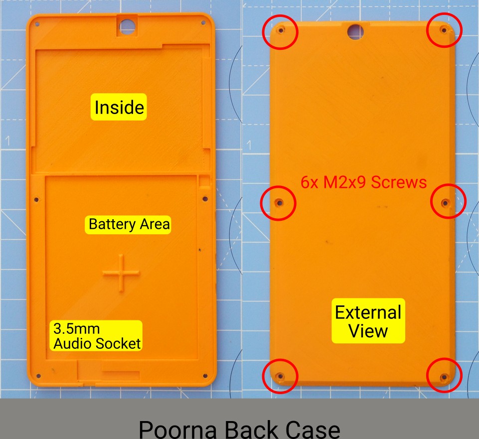
The back cover, similarly looks like this:
The 8 MP autofocus camera shoots from the back. There is a hole in the rear cover corresponding to this. Six self-threading M2 screws are used to fasten the back & front case together – resulting in the complete unit.
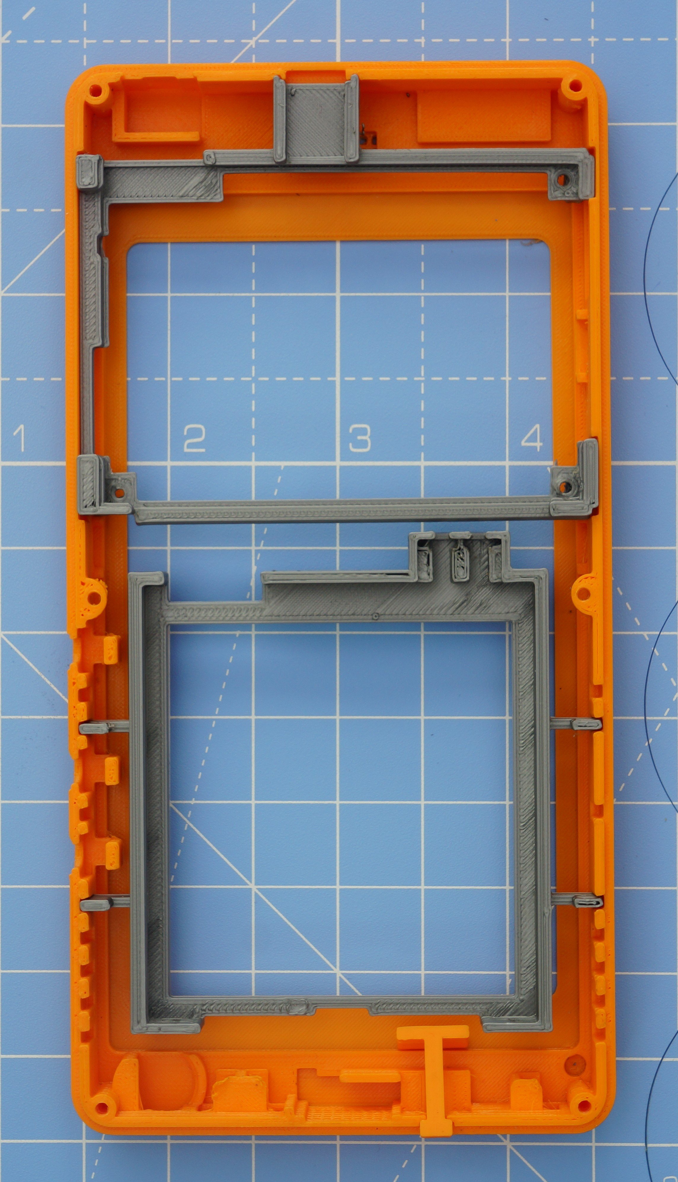
The front case has slots designed for the holders. The following picture shows how things sits together:
The overall dimensions of the fully assembled Poorna phone is 79.5 mm x 157 mm x 14.7 mm. The total weight of the printed parts is about 50 grams. And the overall weight of everything put together – batteries included? About 200 grams.
Ok – enough talking. Let’s start putting together the thing, shall we?
Assembling the Display Module
Kite includes a 5” 720p display module with integrated 5 point capacitive touch panel, plus a display adapter board and a couple of flex cables, pictured below:
Mobile displays are “fast moving” items. Meaning, that they undergo frequent design changes. They can also go out of production rather quickly, and at inopportune times. There are no “long life” warranties associated with them. When longer life is a requirement, the common solution is to pick an “industrial” display. In general, industrial displays are bulky and generally not suitable to build a compact device.
To combat such uncertainties, we need a design that can change with times. We rely on 3D printing to make the phone, so that can take care of changes in physical dimensions. But what about the electronics, and interfacing?
KiteBoard includes a generic display connector to solve this problem. An intermediate display board adapts this generic connector to the specific display in use. A flex cable is used to connect the KiteBoard to the display board. Problem solved!
KiteBoard’s display connector natively supports MIPI DSI displays. Mobile displays use this standard extensively, so there is no need to do any fancy high speed signal conversions. The display board includes a couple of voltage regulators, and a level converter for the touch panel IC (which runs at 3.3V, as opposed to 1.8V for the KiteBoard). For the curious, the schematics of the display board are in kite-design-v01.zip.
Putting together the display module takes a few simple steps, and doesn’t require any tools. First, align & place the display board over the display module. Then, connect the narrow flex cable of the display module to the corresponding connector on the display board. The flex cable is slightly longer, but it works well. The narrow flex cable corresponds to the touch panel (if you zoom in you’ll see the SDA, SCL labels…)
Next, use the display flex (it’s a 42 pin 0.5mm pitch FPC cable – as a quick hack we cut a commonly available 50 pin cable carefully to get this) to connect the wide flex cable on the display module to the corresponding connector on the display board. At each end, you need to open the white flap gently, insert the flex cable, and close the flap. It’s best to connect the flex on the display board first, and then connect the other side. Now, our setup looks like this:
Unlike the display flex, the Display Board flex is a custom FPC cable. It is a two layer flex cable, designed to carry impedance controlled signals with proper reference planes. Proper design of flex cables is important for carrying high speed signals. There are stiffeners over the connectors – this makes the ends sturdy.
In preparation of the next steps, connect The Display Board Flex cable onto its corresponding connector on the display board. Note that I have bent the flex cable a bit. This is useful to connect that end to the KiteBoard later (this will become clear in a few steps). This finishes the display module assembly. Our setup now looks like this:
Time to install the display module assembly into the front case. Here are both of them, side by side.
The display module sits nicely inside its slot, and snaps into place.
At this point, we are done with the display module. We will connect it later to KiteBoard.
Adding Audio & Buttons
Next, let’s take the vibrator, speaker, microphone & earpiece and place them close to their final location.
As mentioned earlier, the front case has a slot for each one of the audio components. These components are small. Holders for the micro connectors (1mm pitch male shrouded headers) are designed into the front case to ensure that they are held in place.
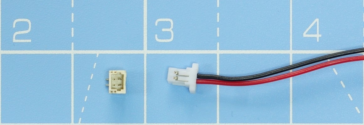
There’s a small story around how we ended up choosing these connectors. In any particular build of Kite, we expect that these components won’t change much. However, a maker may want to customize other aspects – like the many back cover customizations that we have shown in our earlier video. To make it easier to connect/disconnect these audio components, we needed two pin connectors. Searching online got us a few possibilities, but we didn’t find anything that met our exact needs. Maybe we didn’t search hard enough. Luckily, we got 1mm pitch tiny board to wire connectors in the local market. No crimping required, no special tools. A single wire assembly looks like the below picture. These work reasonably well for now, but it’s an area that needs some improvement.
Coming back to the components… The vibrator, and the connector for it, is next inserted into its slot. Do the same for the speaker and the microphone.
The microphone is quite tiny. I generally use a small tweezer to put it in place. There is a small hole on the face of the front cover, through which audio is picked up by the microphone. This is visible in the design files. The hole is so tiny that it didn’t make sense to label it in the images.
The earpiece also sits nicely in the slot. The front face of the earpiece has a sticker that can be peeled out. This can be used to securely attach the earpiece to the front cover. As a temporary measure, I use a bit of tape to hold the earpiece in place.
Brains and More!
We are now ready to prepare the “brains” of the device – the KiteBoard.
KiteBoard has separate connectors for various interfaces. This makes it useful out-of-the box. These connectors cover all the areas of customization:
- a display connector
- two camera connectors
- 120 pin expansion connector
- battery connector
- vibrator connector (solder pads)
- u.FL/IPX connectors – one each for GPS, WiFi/BT and 4G
KiteBoard also has a micro USB connector, a SIM card slot (microSIM form factor – push push type), and a micro SD card slot. KiteBoard is designed to be usable standalone. If you pop in a SIM card, connect the antennas, and supply power, then it will boot to Android directly. But that’s not something we will do right now.
Let’s get the KiteBoard into the picture, and continue with the assembly. This step needs some soldering, shown in the picture below:
Using small pieces of wire, and a soldering iron, let’s connect the pogo pins to the battery connector. The two pogo pins will connect to the +ve and -ve terminals of the battery. These pogo pins will sit inside the battery holder, allowing us to swap batteries later.
The vibration motor pads are soldered to a long pair of wires connecting to a male micro connector. Ideally, we shouldn’t need soldering on the main board. A design revision is required to achieve this.
The prepared KiteBoard will sit in the 3D printed board holder. Let’s get that into the picture now.
Next, insert the KiteBoard into the board holder. Two screws (M2x5) keep the KiteBoard securely in place.
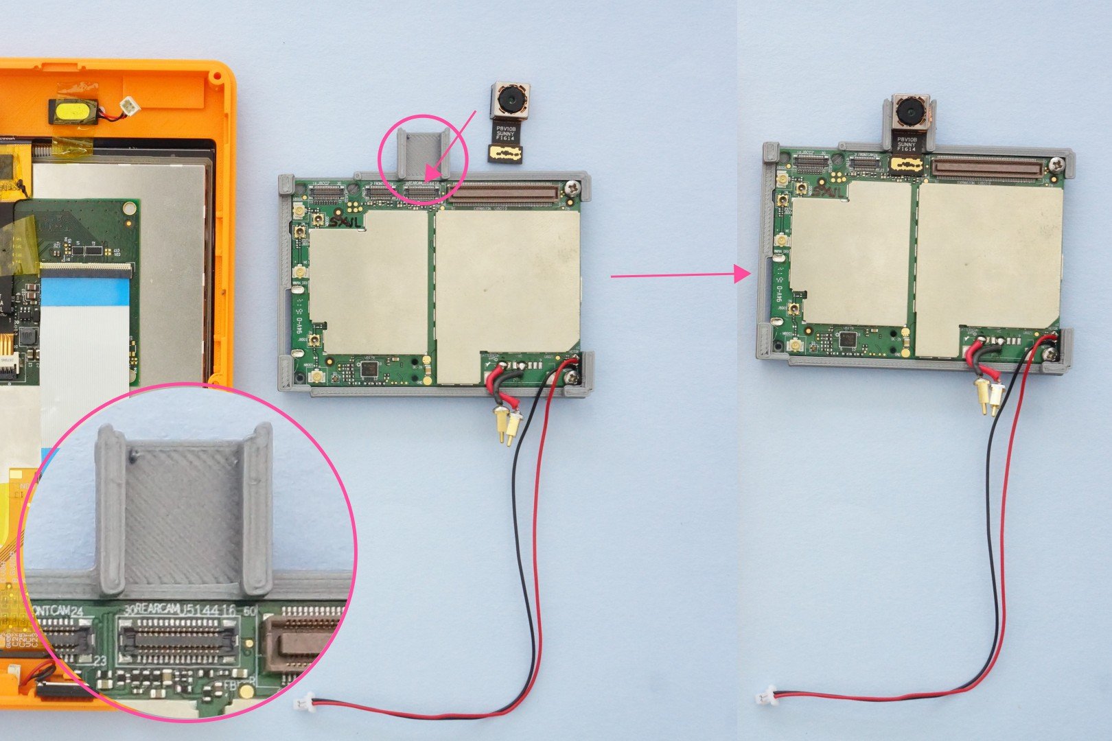
Kite includes an 8 MP autofocus camera module. The board holder has a slot designed for the camera module. The camera module sits inside the slot. The short flex cable is inserted into the corresponding camera connector on KiteBoard.
The GPS antenna connector is on the bottom side of the KiteBoard. The GPS antenna in the kit is Sanav’s D-10, a tiny ceramic GPS antenna. It comes with a 4cm long cable terminated with an IPX connector. The cable is slightly longer that what we needed, but we didn’t have any problems with it. We found that the antenna cable would twist & break. To compensate for this, we put a small blob of hot glue where the cable attaches to the antenna part. This provides mechanical stability, but doesn’t impact the antenna in any other way. The GPS antenna is connected to the uFL connector on the bottom side of the KiteBoard.
The WiFi/BT antenna (TE connectivity part no 2118309-1) is connected next – to another u.FL connector on the top side of the KiteBoard.. The cable is quite long, but nothing that won’t fit inside.
If you need to use a SD card, you will have to connect it to the board now. The case design doesn’t make the SD card slot usable from outside. I know - stupid of us to overlook this – but we’ll fix it eventually. At this time, the setup looks like the below picture. In the next step, the board holder will be placed into its slot in the front cover – so this is a good time to have a look at that as well.
The board holder is next placed into its slot in the front cover. While doing this, the GPS antenna and the WiFi/BT antenna are carefully placed in their positions. Note that the WiFi antenna cable is routed from the side. The connector for the earpiece must be accessible after this (it comes over the WiFi antenna, as shown in the picture below). We will need it later to connect the earpiece. With all this done, our table looks like this:
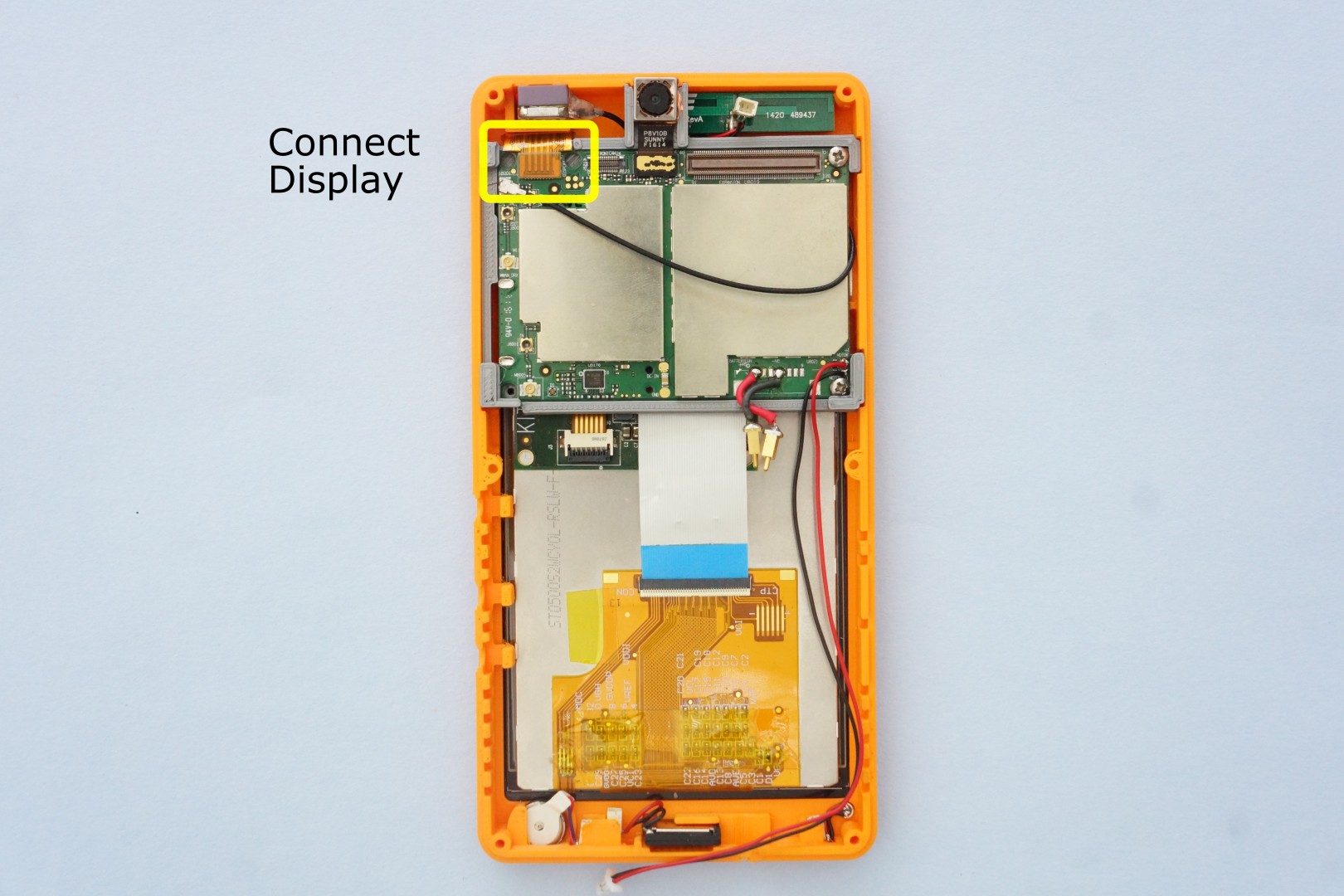
The display board’s flex can now be connected to the display connector on KiteBoard.
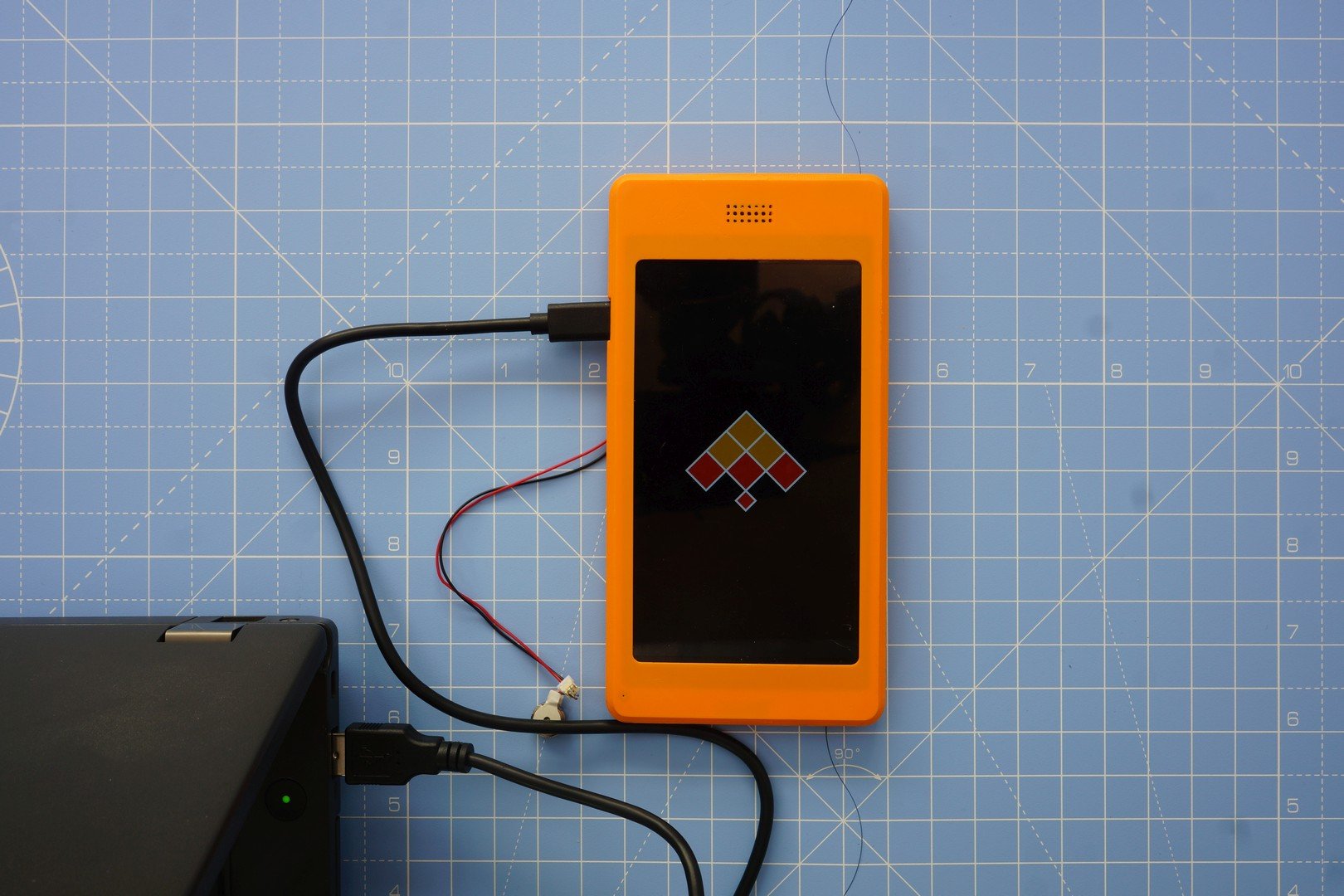
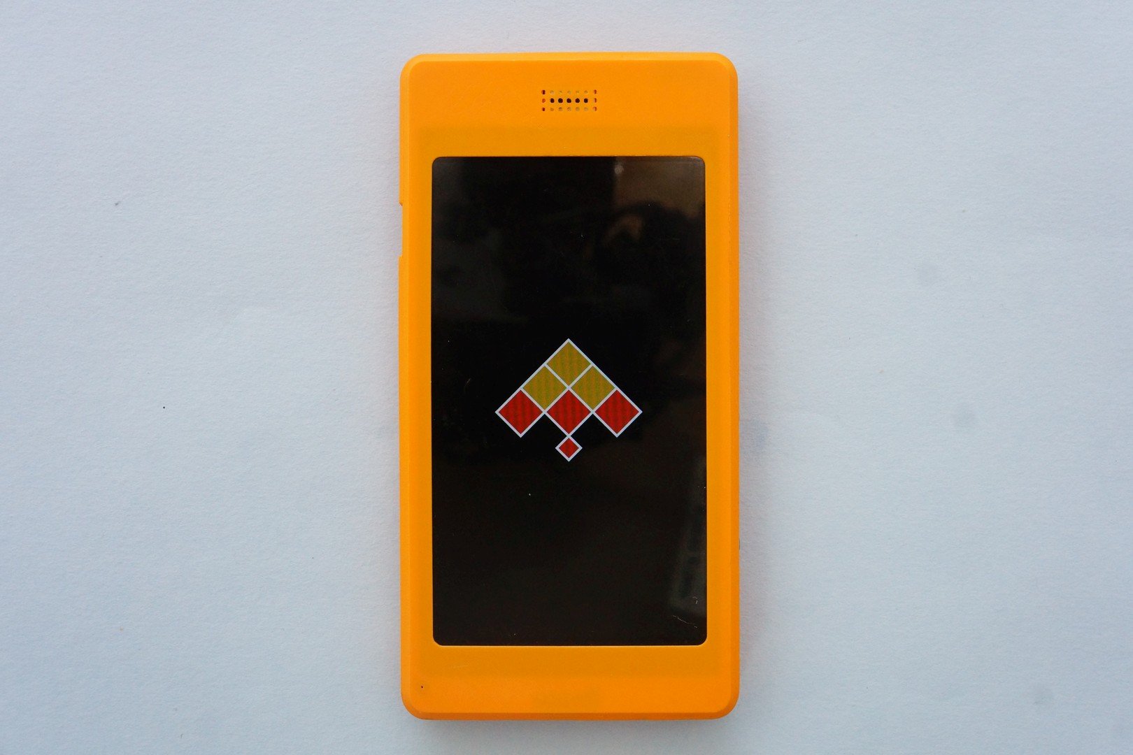
We’ve been assembling the kit for a while now, without seeing much results. Boring, right ? Now that the display module is connected to KiteBoard, is it possible to verify if it works? You bet. Connect a cable USB to the KiteBoard – with the other end connected to a laptop – and you should see the Kite logo on the display.
Good job! Things are fine at this stage. With the USB cable, it won’t boot to Android yet – but then good things in life come a bit slow…
It is very useful to be able to verify the display at this time. Imagine assembling the whole device & then figuring out that display does not work. If you saw the timelapse video, you would remember that the device is powered on only in the end. Powering ON the display in middle of the video would have killed the video… I added this verification step after I finished shooting the timelapse, hence the new background.
The expansion board stacks on the KiteBoard, mating to the 120 pin connector. The picture below shows both sides of the expansion board.
The expansion board makes the KiteBoard usable for everybody. It converts and exposes the platform I/O pins at a usable 3.3V level. 3.3V and 5V power are provided for user electronics. Platform audio capabilities are also made accessible by the expansion board. The expansion board is, in fact, the unsung hero of the whole modularity angle. And will remain so in this post; we're building the base model after all !
The bottom side of the expansion board has many components – mainly voltage regulators and level conversion circuitry. Also a micro SIM connector (this is the second SIM card), push push type. The top side is designed such that components need not be mounted on it, when used in a phone style case.
The expansion board has a few significant footprints, all using standard 0.1 inch spacing:
- a 40 pin Raspberry Pi HAT compatible connector. This exposes the platform pins, after level conversion to 3.3V. KiteBoard runs at 1.8V, so conversion is required. The level converters also provide useful ESD protection.
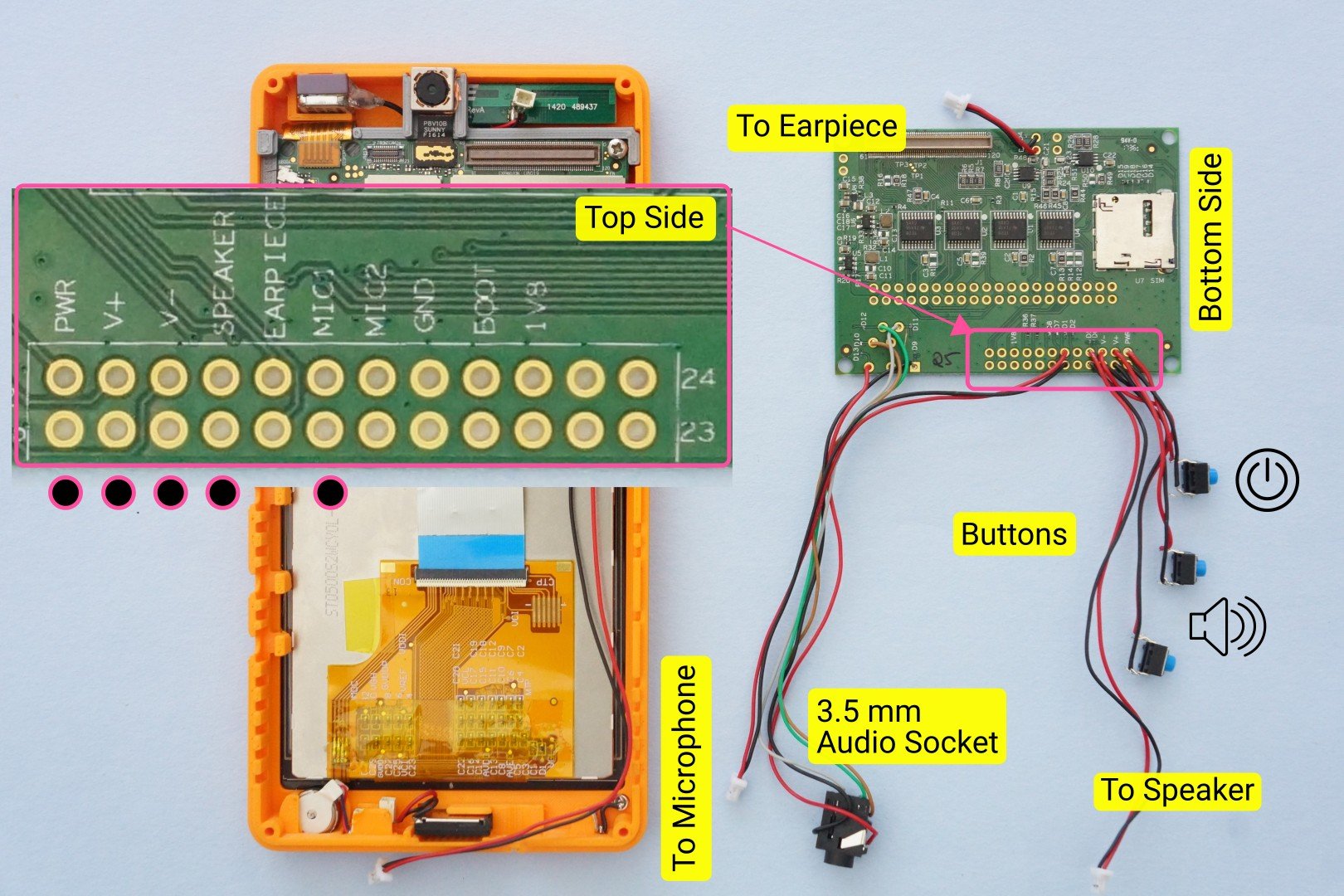
- a 24 pin Audio & button connector, with useful pair of pads for
- Power button
- Volume up button
- Volume down button
- Speaker
- Earpiece
- Microphone
- 5V DC power. This can be used to power the KiteBoard using an external power source. The KiteBoard can take power from three sources: battery, USB, and DC(5V). We won’t use the 5V option in this build.
- Standard 3.5 mm audio socket (Digikey part number SJ-43515TS)
A bit about Raspberry Pi compatibility before we proceed further. KiteBoard is not based on the same SoC as the Raspberry Pi, and works at 1.8V level, so we can’t be 100% compatible with the Raspberry Pi. That said, most shields that use I2C, 3.3 & 5V power, SPI and UART interfaces will work. I2S can be made to work with some wiring from the display board, but that’s not straightforward. We are planning to fix this in the next revision of the KiteBoard.
Connecting Audio & Buttons
Soldering is needed for the audio components. We need to wire a few parts:
- Power button (2 wires)
- Volume up button (2 wires)
- Volume down button (2 wires)
- Speaker (2 wires)
- Microphone (2 wires)
- Audio socket (5 wires)
- Earpiece (2 wires)
The picture below shows the wiring in detail. Note that the wires are routed from the bottom side.
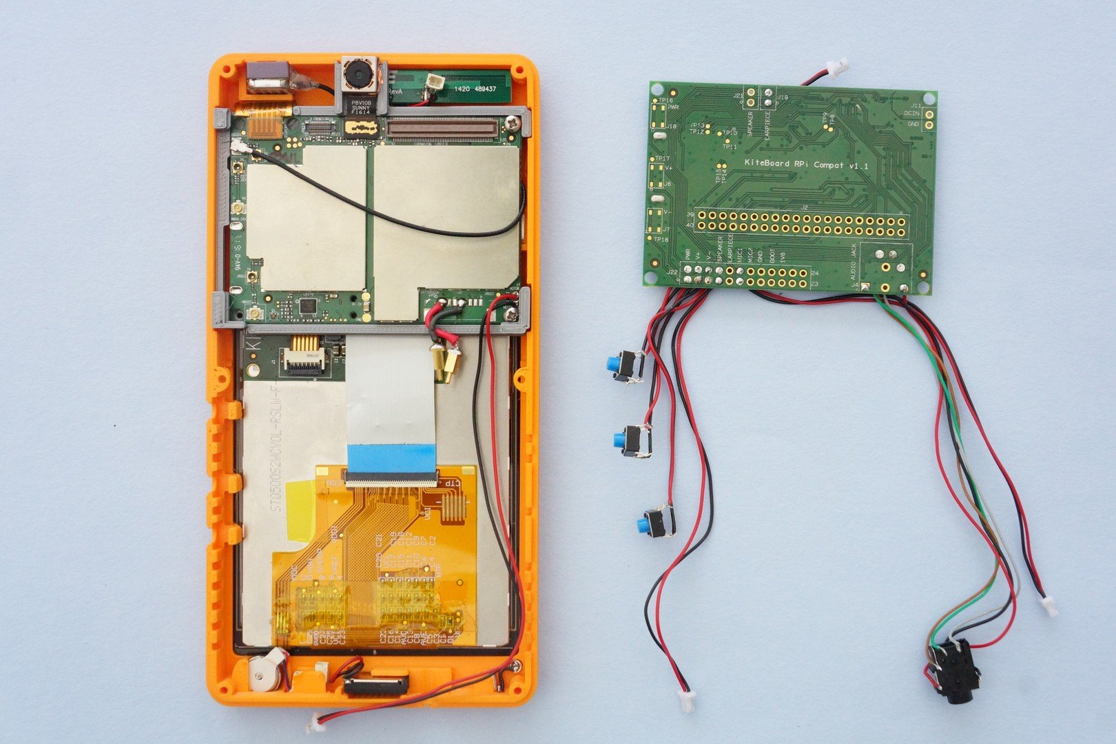
If we flip over the expansion board into the orientation required for the next step, the setup will look like this:
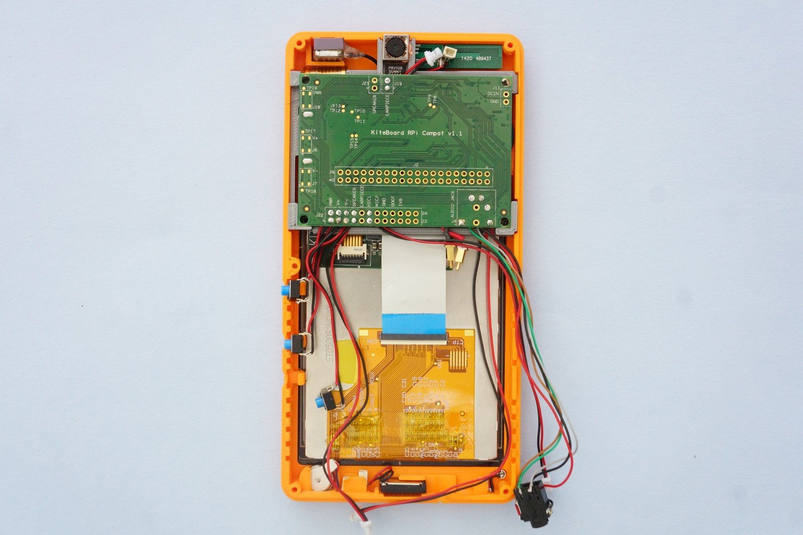
The expansion board can now be mated with the KiteBoard. The board holder has a slot for the expansion board. The expansion board sits nicely in this slot.
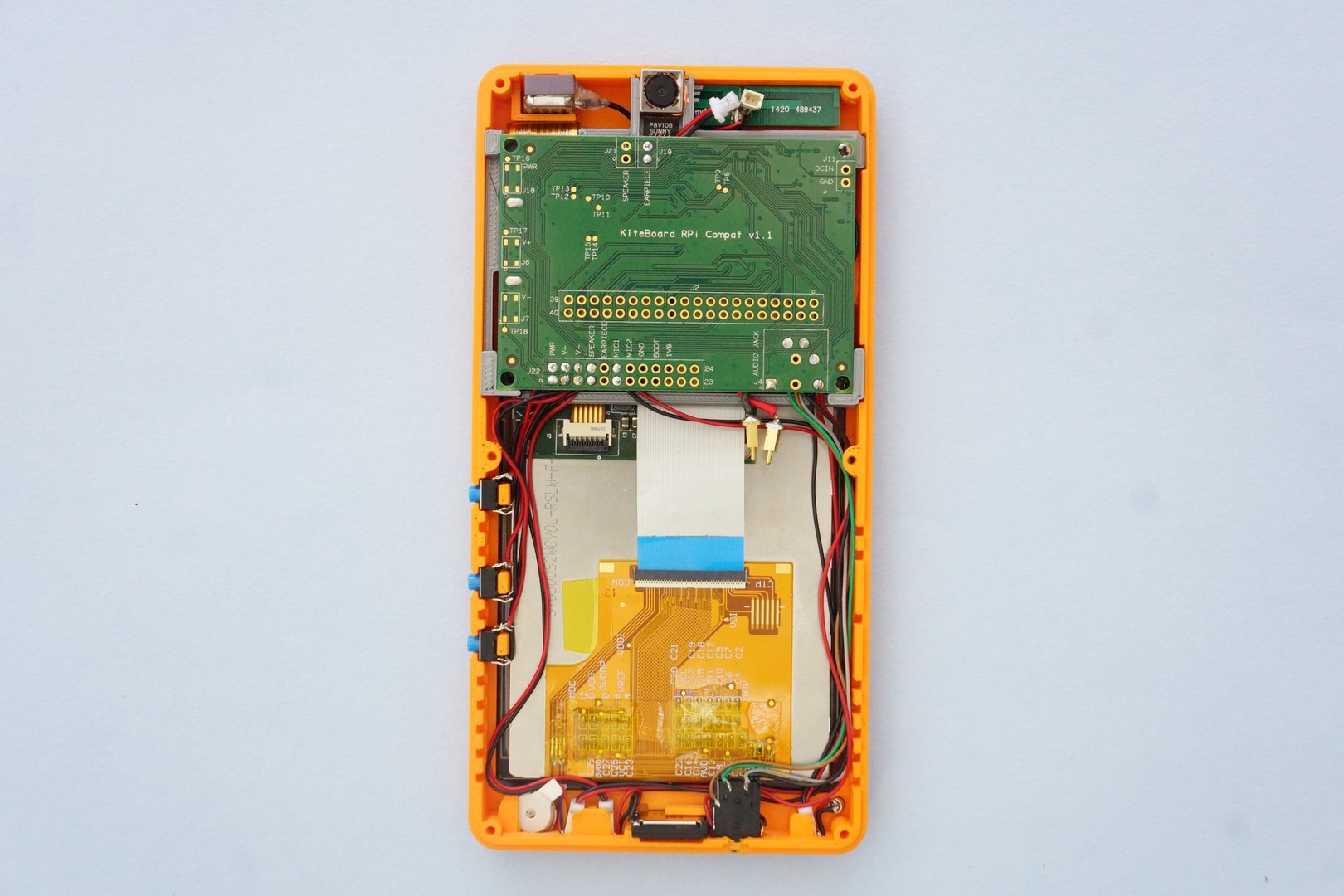
Next, insert the push buttons into their slots, plus connect the vibrator, speaker, and microphone. Note that the connectors for the audio parts are inserted sideways. Finally, insert the wired audio socket in its designated slot. After routing all the wires closer to the case, we end up with an arrangement similar to the following picture.
Battery Matters
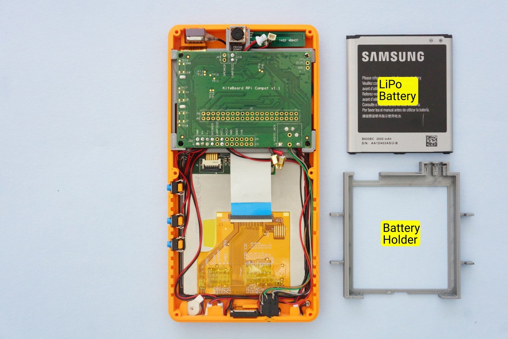
KiteBoard works with standard Li-Poly batteries. Sourcing compact standardized batteries (apart from some standards like BL-5C) is a pain – folks building products generally need to customize batteries to their requirements. Luckily, off the shelf replaceable batteries are available for various phones. We prefer replaceable batteries, as these can be swapped with a minimum of fuss. I found a 2600 mAh battery for various Samsung phones – and purchased it from an online store.
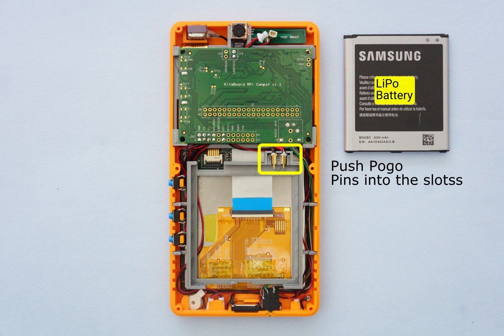
To keep the battery in place, we designed a battery holder, which is 3D printed. The battery holder has two slots for the pogo pins. When the battery is inserted into the slot, the pogo pins make firm contact.
The battery holder is designed to fit snugly inside the front case. The front case has “ridges”. The battery holder has fins that match & slide inside these ridges. The battery holder sits in the front case, as shown below. With the battery holder in place, the pogo pins can then be placed in their designated slots. Carefully note the + and – pins. These need to match the battery.
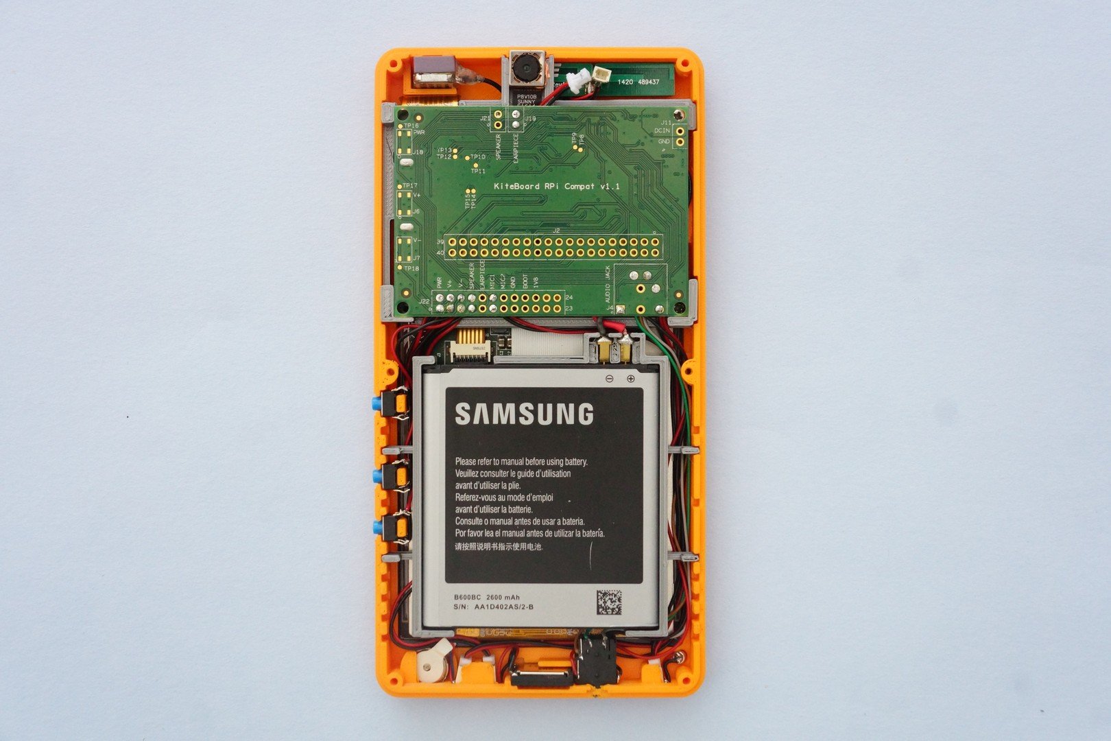
Next, lets insert the battery in the battery holder. The pogo pins will nicely hold the battery in place.
Let's Get on the Network!
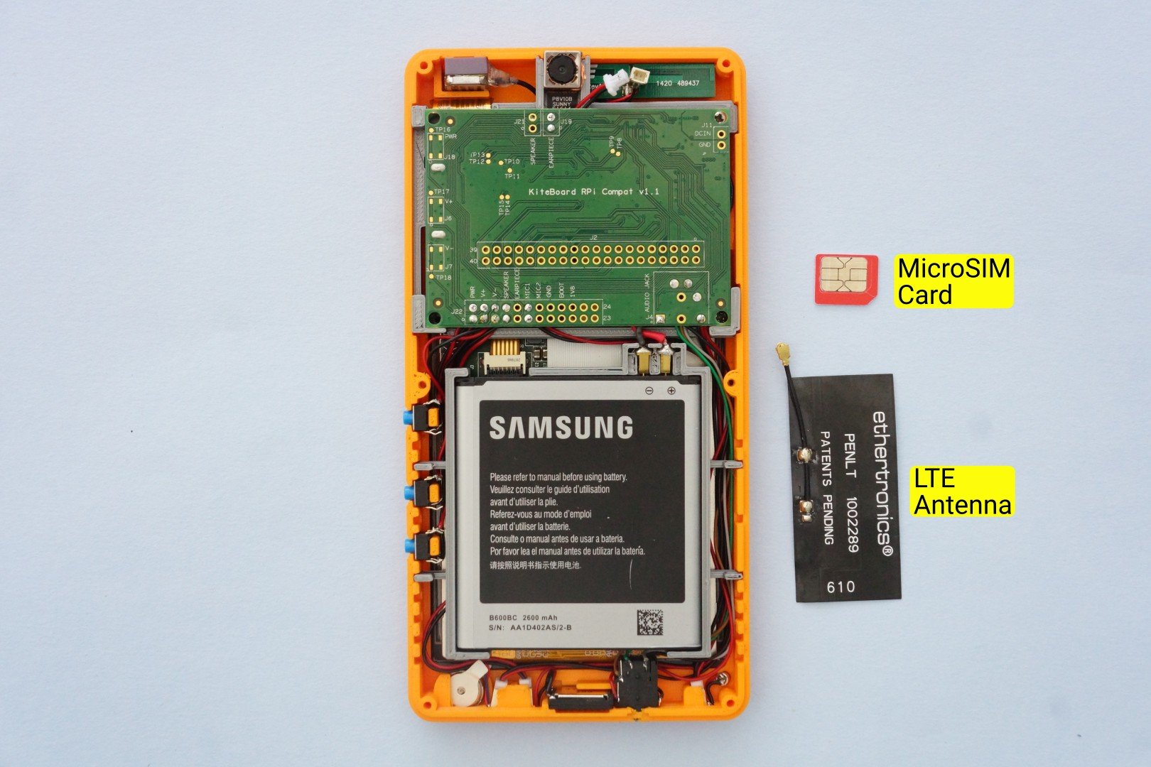
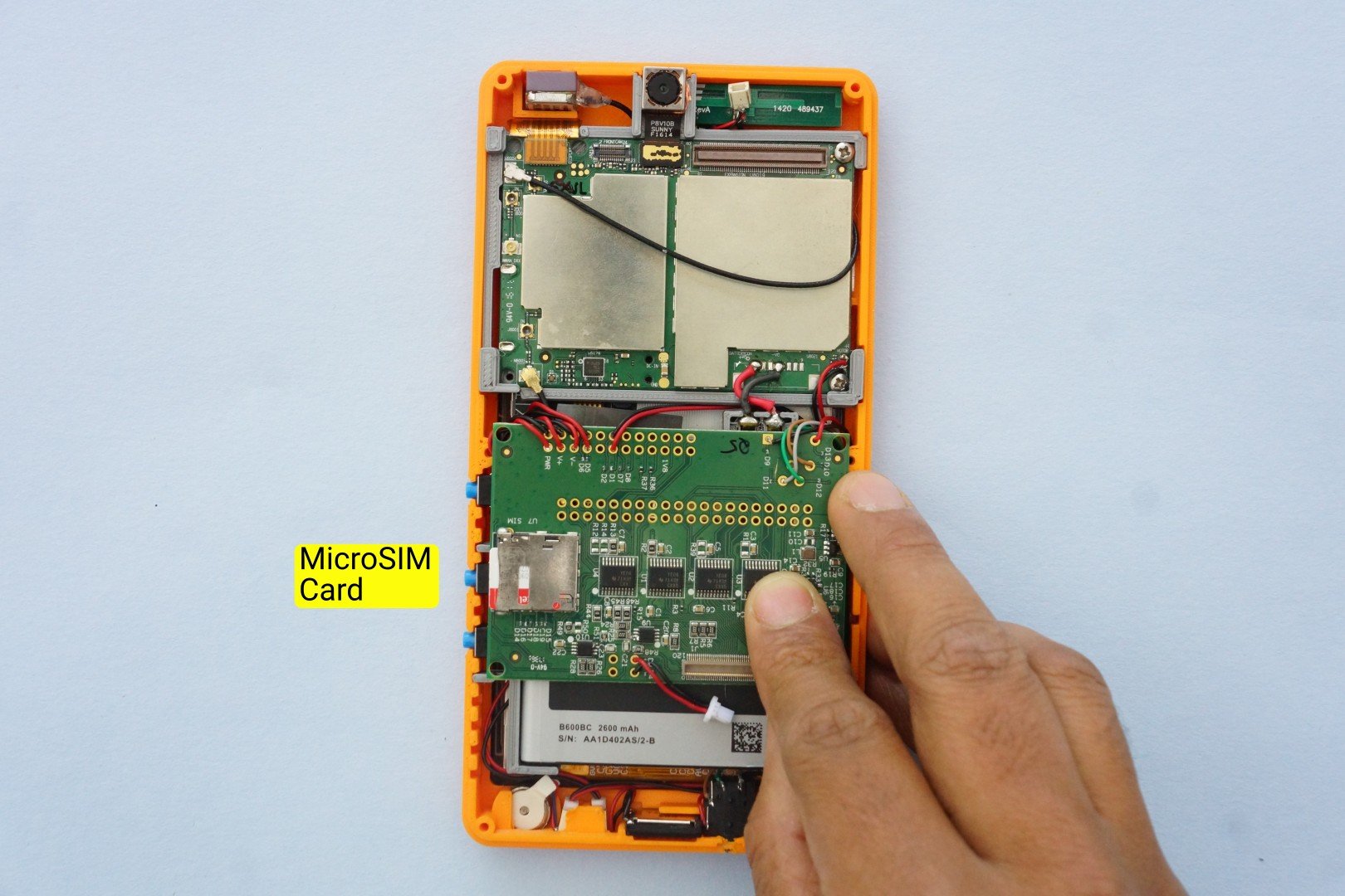
To get on a network, we need a SIM card and an LTE antenna. KiteBoard supports two SIM cards. The second SIM card is routed & made available on the expansion board – on the bottom side.
The LTE antenna we have are using for now is a penta-band flex antenna from Ethertronics (P/N 1002289). This supports all the LTE, 3G and 2G bands supported by KiteBoard. It’s an off the shelf part. Plus it’s available in a single quantity in DigiKey. All good reasons to use it in the kit!
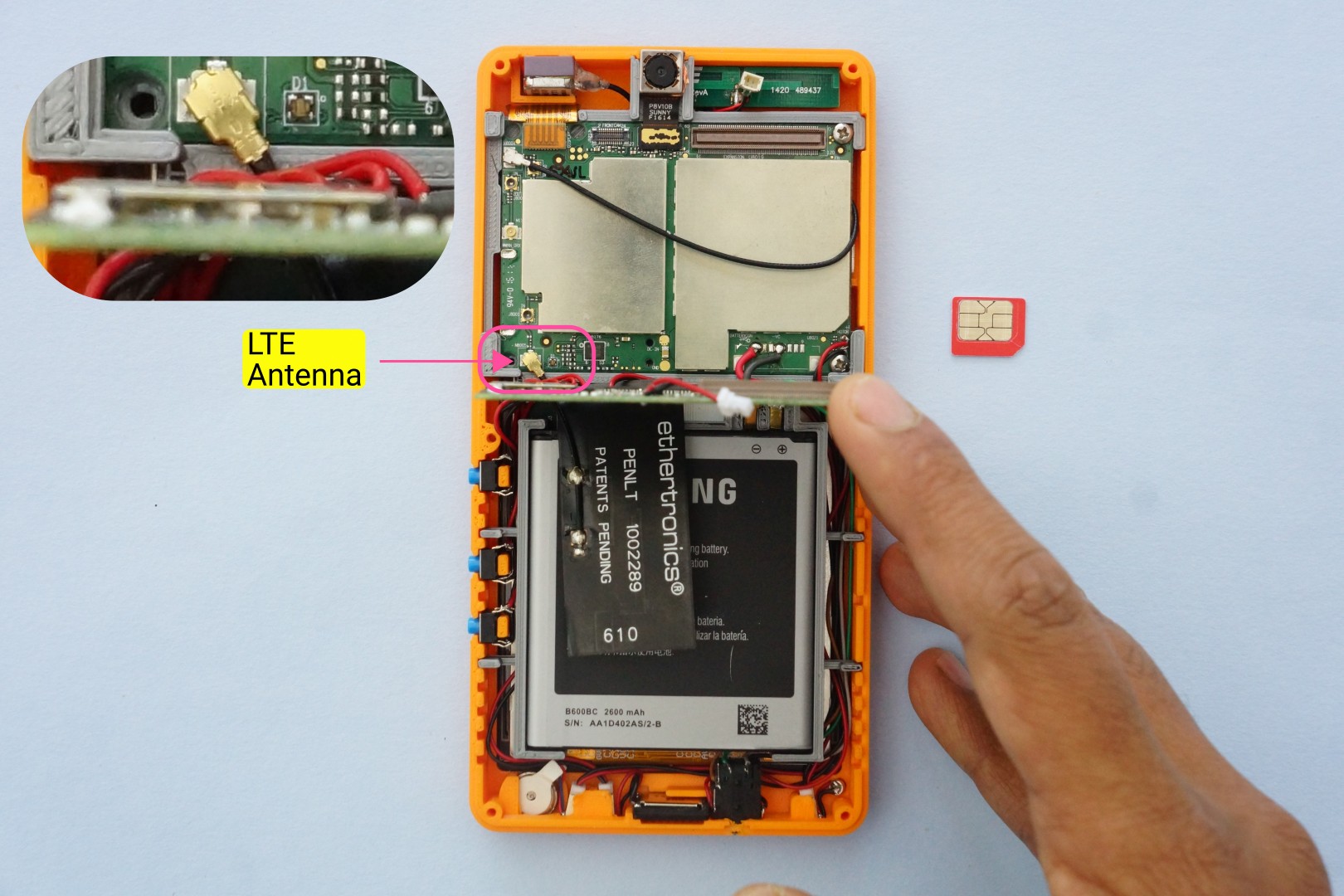
The LTE antenna connector is on the KiteBoard. With the expansion board plugged in, it is not accessible. To plug in the antenna, we unplug the expansion board. All the wiring stays in place. We can now connect the LTE antenna. The antenna sits on the battery, and connects to the KiteBoard. The antenna cable is quite short, but that’s not a problem for now.
Next, we insert the SIM card into the microSIM connector on the bottom side of the expansion board. It’s a push push type connector. Feel the satisfying click as you push it in…
When show the phone, folks generally ask me – “where do I insert the SIM card?”. We designed the case to have the SIM card completely inside, as we don’t expect our users change SIM cards often. This simplifies the enclosure design.
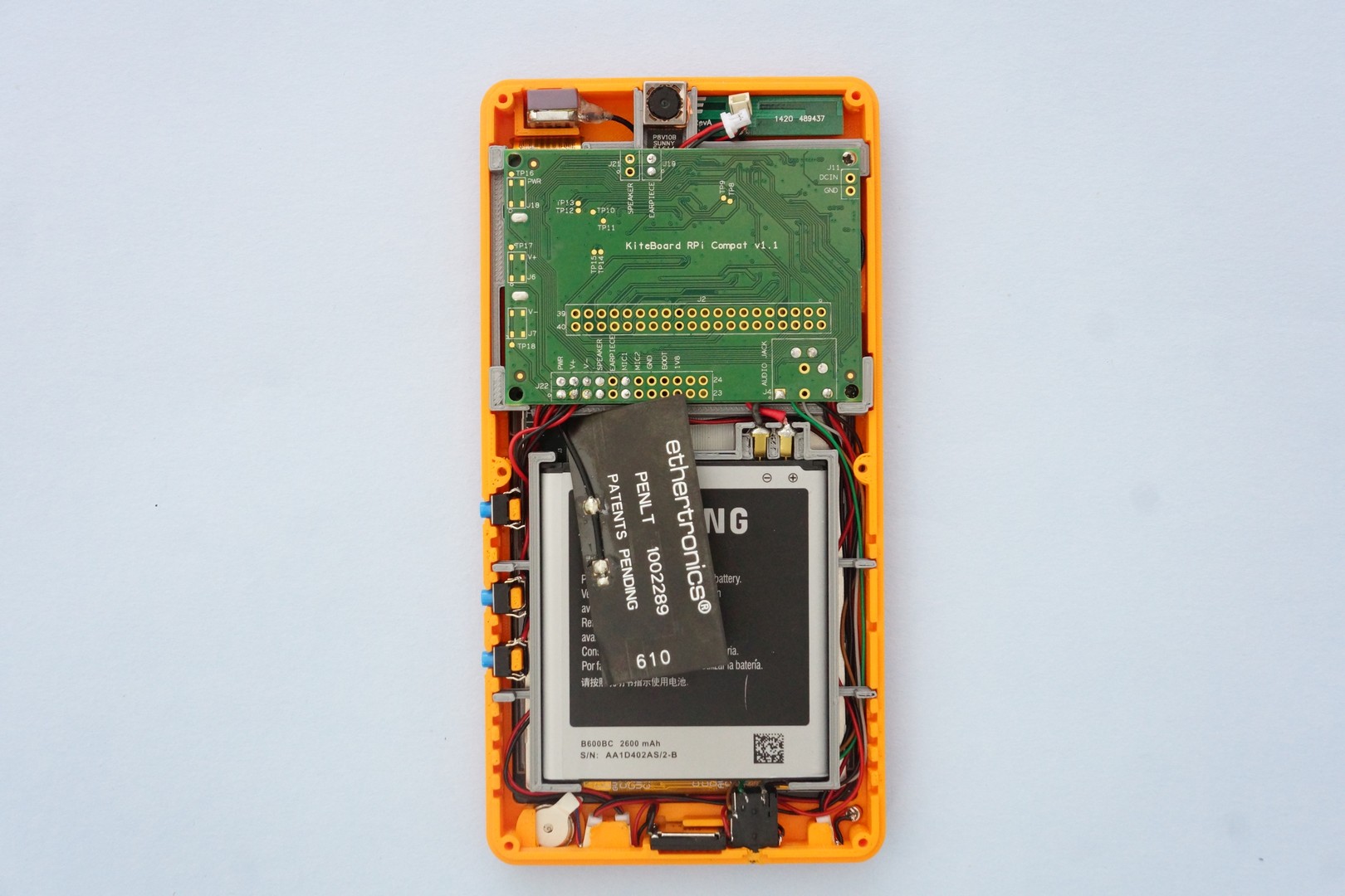
We can now connect back the expansion board to the KiteBoard again. The antenna appears to float in space.
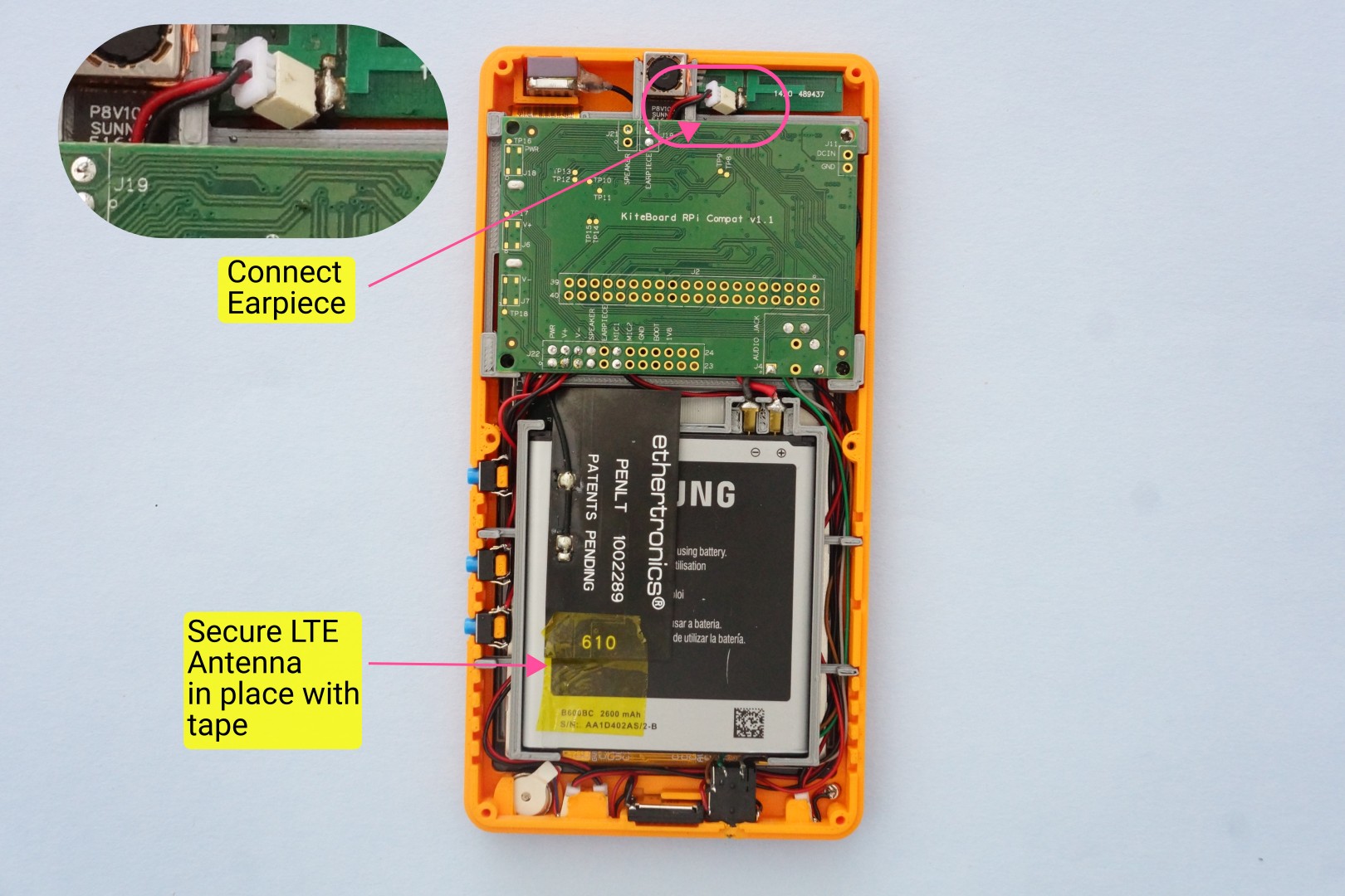
There’s nothing that a bit of tape can’t fix – secure the antenna to the battery with a bit of tape. This solution isn’t ideal - there is still a slight bend on the antenna.
The antenna comes with adhesive backing, and is intended to be securely pasted in place. Sticking the antenna on the battery would deviate from the concept of having a swappable battery. A complete solution to this will require customizing the cable, and some more work to decide a reasonable place for it – that’s work-in-progress. For now, a bit of tape works. Let’s connect the earpiece as well.
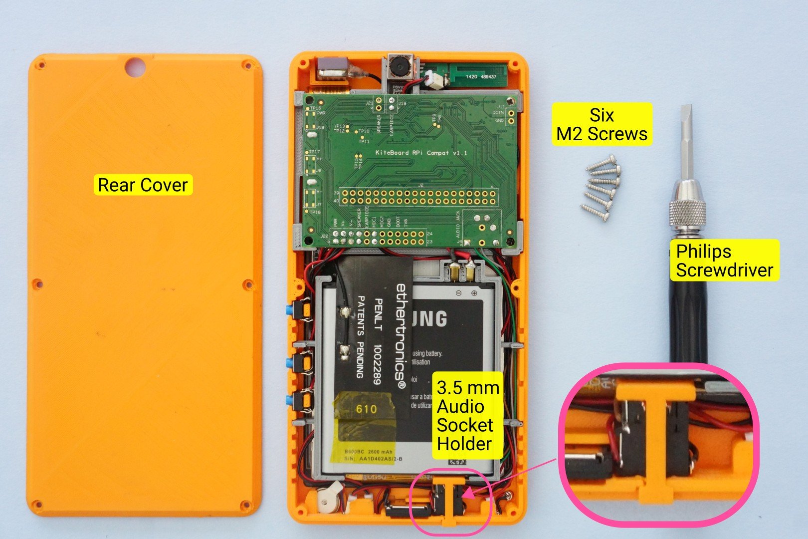
Time to close the back cover & complete Poorna. We’ll need a screw driver, and six M2x9 screws. The 3D printed parts include a small piece that helps keep the audio socket in place. We don’t realize this, but pushing an audio jack inside the socket results in a considerable amount of force. This piece is designed such that audio socket stays in place securely. Let’s place this part in its place.
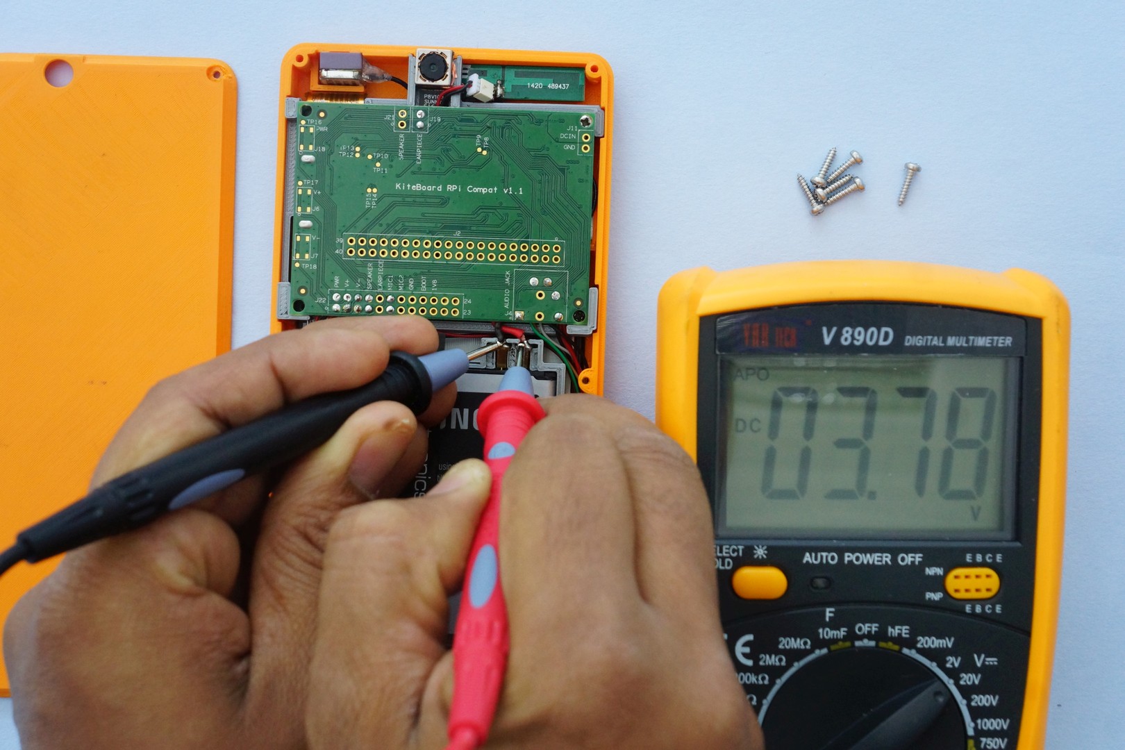
Are we ready to close the cover now? Almost. We’ll do one last check with a multimeter – ensuring that the pogo pins are making contact, and that the battery is sufficiently charged. The battery shows 3.78 volts (more than 3.6 is generally enough), so we are ready to go!
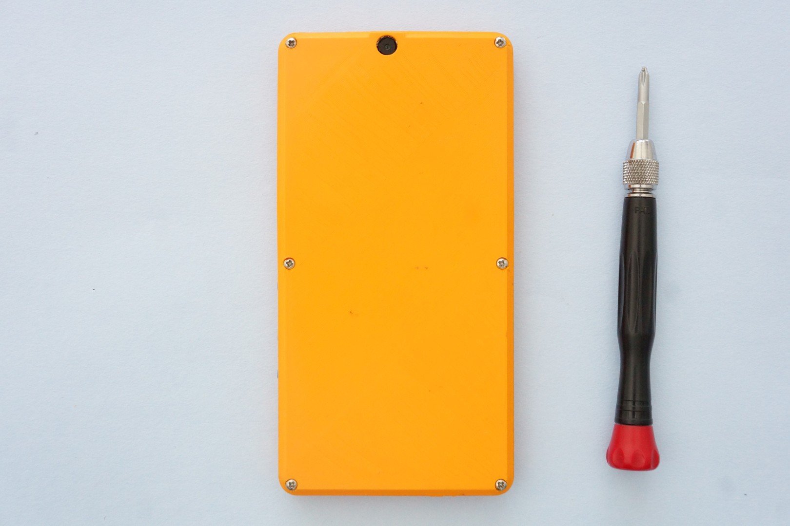
\Now we place the back cover over the front cover. There are “lips” on the front cover to make sure the back cover sits nicely. Use the screw driver to put in all the screws. And then, drive the screws in all the way! Done with the screwdriver! We take a moment to admire what we have built.
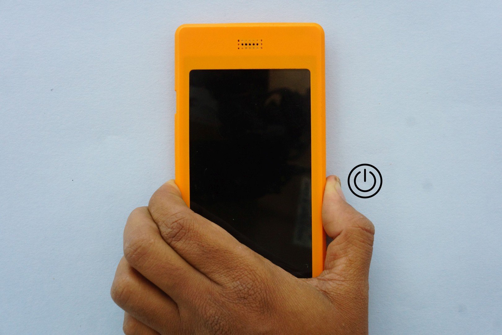
Showtime! Press & hold till you feel the vibrator announcing that the phone is coming alive!
Almost immediately, you’ll see the splash screen. Yahoo!
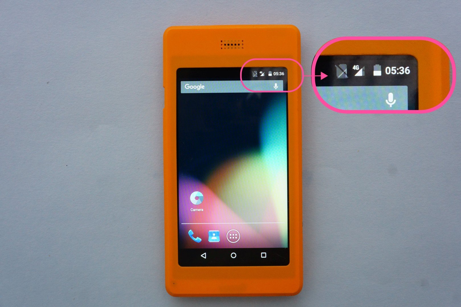
The phone will boot to the lock screen. Unlock the screen. Verify that you’re connected to 4G. That’s it, we are done. Enjoy android apps on Poorna, your fully custom-built phone. The full functionality of the SIM is available: data, voice calls & SMS.
Thanks for reading this far. Do remember that this is just the beginning. I have barely scratched the surface. Kite is capable of much more!










Leave a comment here