
After we built Poorna, our base model, we had a bit of a problem. We had engineered a lot of flexibility into our design. Folks asked us, “what can you do with this?”. My typical response, invariably, would be “a lot – anything, in fact”. It took me a while to figure out that this was not working…. “anything” is “nothing” unless shown to be “something”. After that realization, I set about building some demos.
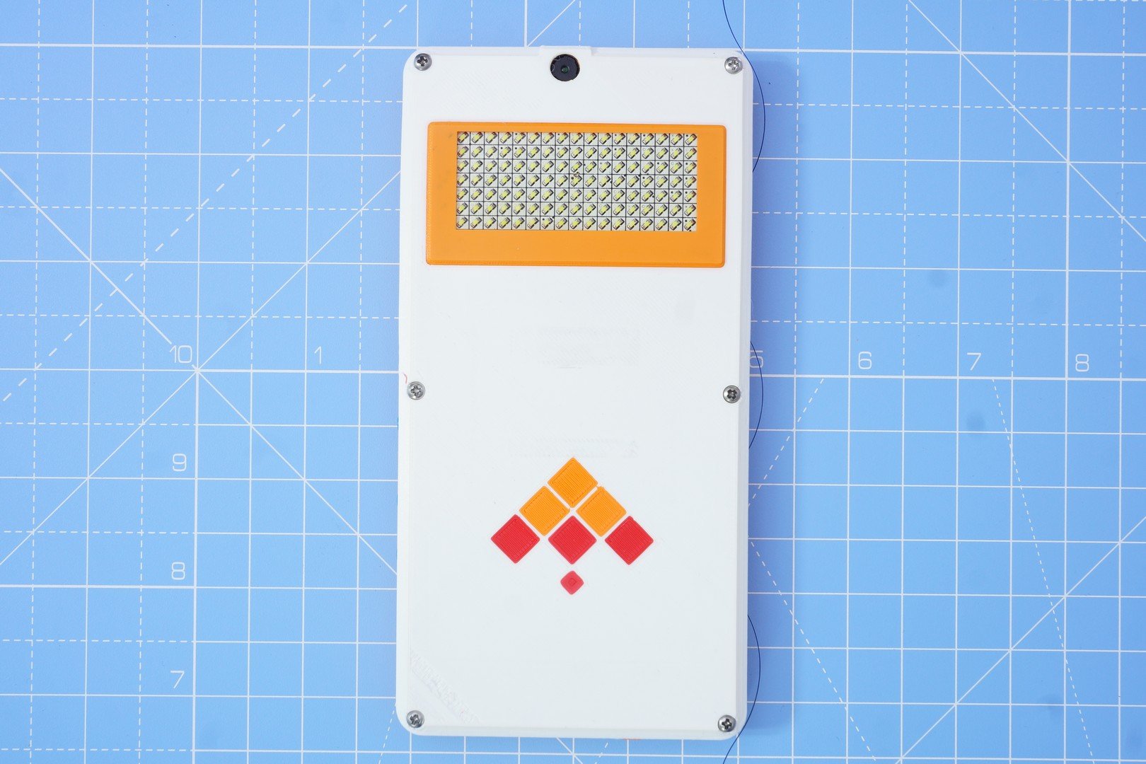
Explaining a new idea (and certainly something with wide possibilities like Kite) to folks is a lot of work. In today’s world, getting attention & creating a first impression is very important. After racking my brains for a while, I hit upon the idea of adding a name badge to my phone. This is the same model that’s shown in my pocket in our intro video:
![]()
We call this model “Minchu”, meaning “Lightning” in the Kannada language (spoken in Karnataka state in India; Bengaluru/Bangalore is the capital city, and also our base). The idea behind this name will be explained towards the end of this post.
I have visited Shenzhen, in China, a couple of times. Each time, I have come back impressed with the bewildering variety of stuff sold at Huaqiangbei, all at shocking prices of course. My favorite trinkets, purchased there four years ago, were a few scrolling LED badges. Back then, I had not seen these online, but now Aliexpress seems to have a lot of choices. These badges feature bright LEDs of a single color – red (cheapest), green, blue and white(30% more expensive than red). They pack a lot of SMD LEDs, worked off a battery, the whole thing was programmable with a USB cable, and included a rechargeable battery plus a magnetic clip at the back. In any case, I was hooked - I must have purchased 10 pieces, at-least, at bargain prices! They were a big hit in my office as well. I sold a few (at cost) to a few lucky colleagues. Walking around, with one pinned to my shirt pocket, was a surefire way of grabbing attention at conferences. A great conversation starter!
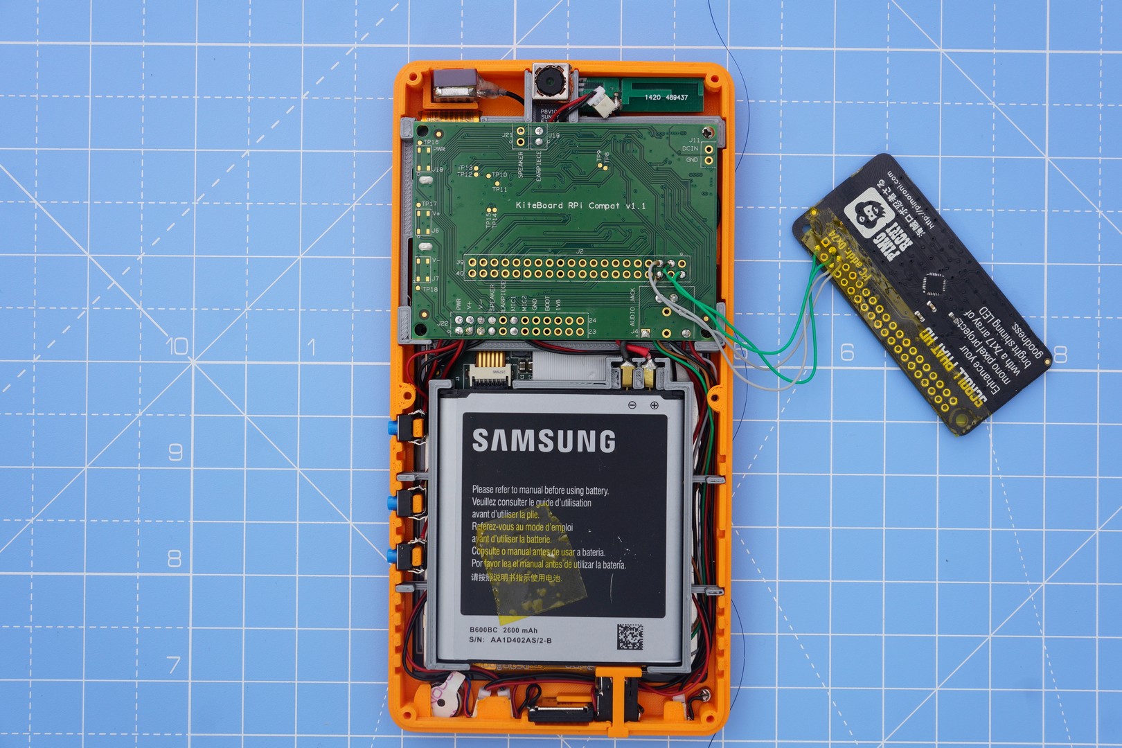
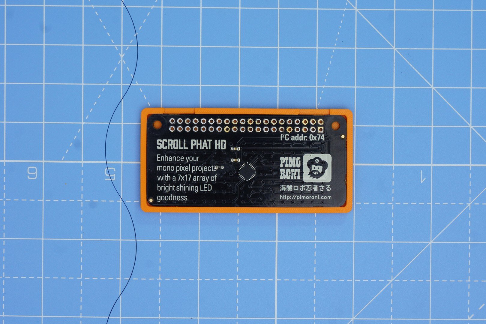
These commercial name badge is programmed via a USB cable. The badge uses a PL2303 serial to USB converter. I could have used the same name badge itself, with a bit of reverse engineering. However, I was more interested in showing off the Raspberry Pi compatibility that we had built. So, I chose to add the Pimoroni Scroll pHAT HD to Poorna.
The Pimoroni Scroll pHAT HD features 17x7 LEDs. It is based on the IS31FL3731 LED matrix driver chip. Prior to ordering, I had a look at the datasheet of the IS31FL3731. A couple of features grabbed my attention:
- Picture mode and animation mode
- 8 frames memory for animations
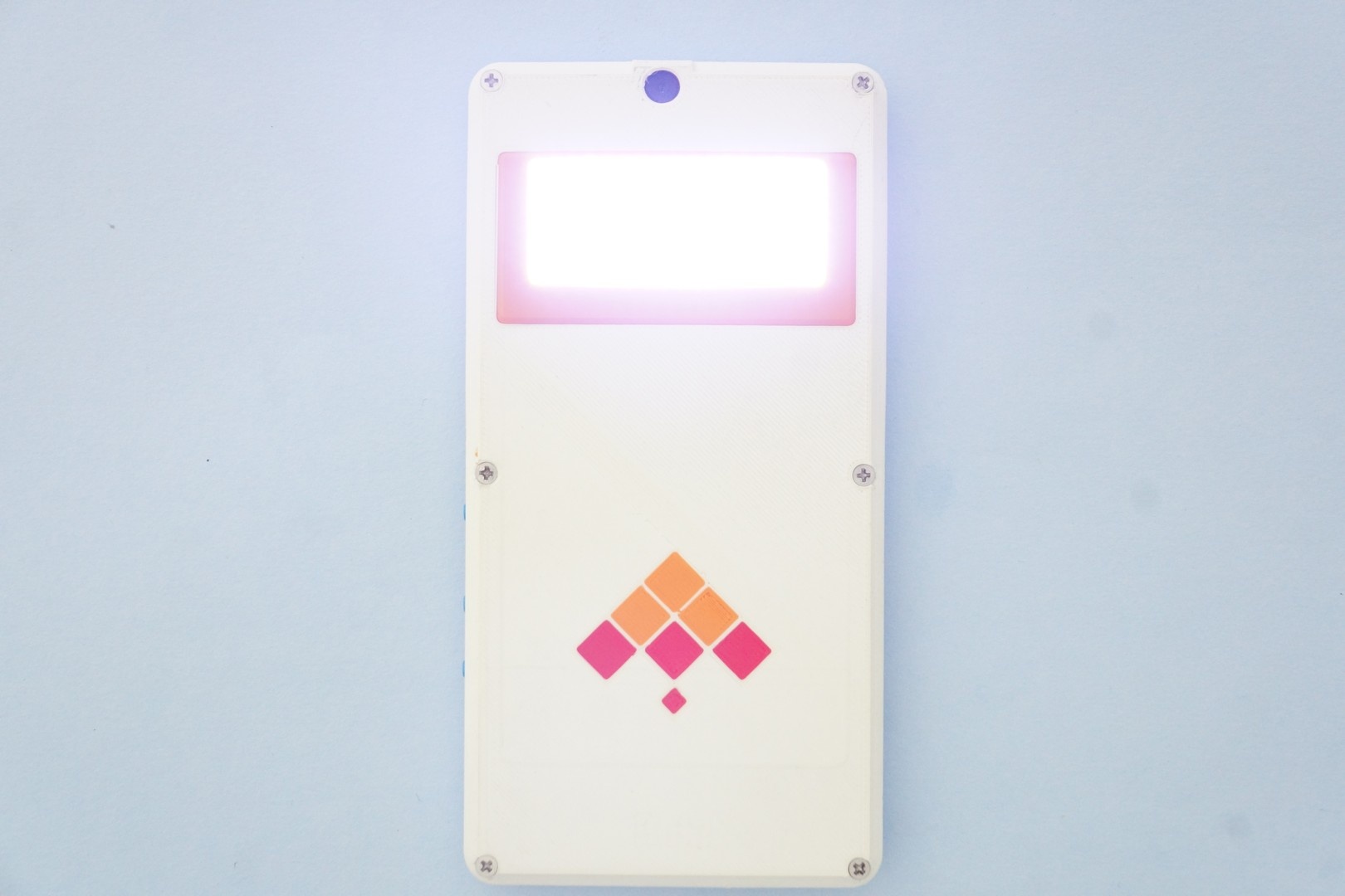
Would it be possible to use these features to animate my name on the pHAT while my phone is in sleep? Kite is a phone platform. It features very low power consumption (<5mA) even when connected to the cellular network. If I could configure the pHAT in “animation mode” & then send the phone to sleep, then the animation would be visible when the phone is in sleep, without any additional CPU usage.
Being the lazy types, I searched online to see if folks were using the animation feature. Nothing relevant turned up. That kind of made sense. Most folks use a Scroll pHAT HD with a Raspberry Pi, on Linux. Animation is typically implemented by repeated draw calls, followed by calls to update(). Generally, folks don’t put the Raspberry Pi to sleep while expecting it to do something useful….
To accommodate the Scroll pHAT HD inside Poorna, we need to modify the back cover. But before we do that, let’s get the electronics to work, shall we? My last update covered Kite, and mechanical assembly of Poorna. However, I didn't say anything about software and interfacing electronics. Most of this post will cover those aspects. All the files referenced in this post are available in minchu-v01.zip.
Information required to interface the Scroll pHAT HD is available at pinout.xyz. Basically, the pHAT is powered by 5V. I2C (two wires – SDA, SCL) is used for communication with the IS31FL3731 chip. The Scroll pHAT HD is generally used on a Raspberry Pi with the headers soldered. To make a compact case, these need to be removed.
With the back cover removed, Kite’s expansion board is visible. We use 4 wires to connect 5V, GND, SDA and SCL signals from the Raspberry pi compatibility connector on the expansion board to the Scroll pHAT HD. What could be simpler? (Note the 4 wires in the picture below)
We need to next verify that KiteBoard can “talk” to the Scroll pHAT HD, as well as implement the required software to get the whole thing to work. Pimoroni maintains a Python module for the Scroll pHAT HD – this works on the Raspberry Pi, running Linux. KiteBoard runs Android; Linux software won’t work directly in our environment. What are our options?
I could, of course port the python library to Android first. To start with, that’s way too much work. Also, after porting, if the thing doesn’t work – do I blame my port, or the hardware?
Fortunately, we have engineered an easy way out: we have a chroot environment, running right inside Android. The chroot environment has Debian Jessie, which can run Python – and so the pHAT examples, unmodified. Inside this chroot environment, you can now test the pHAT almost like you normally would… Could life be simpler? Here are the exact commands:
$ adb root # need root to start chroot environment
$ adb shell start chroot # this sets up some stuff, including SSH too, but we don’t use it below
$ adb shell # commands after this run on the device
# unset LD_PRELOAD
# chroot /data/local/linux /bin/bash
# export PATH=/bin:/usr/bin
# cd /opt/scroll-phat-hd/examples
# ./hello-world.py
Scroll pHAT HD: Hello World
Scrolls “Hello World” across the screen
In a 5x7 pixel large font.
Press Ctrl+C to exit!
Here's the output (Note the USB cable - that's exactly how you'd use adb on your Android phone):
At this point, we have checked the hardware. It is fun to run the other examples too. I like swirl.py – it transports me to a magical time in my childhood – where we would eagerly wait for the TV programmes to begin; the TV would spring to life with Doordarshan’s Signature Tune.
Python is a fantastic, easy to use programming environment. The Pimoroni library does most of the work required for the pHAT. If we can figure out the appropriate register configuration for “animation mode”, then we can easily implement it in python. Page 9 of the datasheet has an overview of the relevant registers:
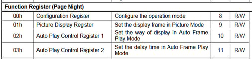
The Configuration Register, and Auto Play Configuration registers are described in detail in page 12. Basically, the chip can work in one of three modes:
- Picture mode – default, used by most projects
- Auto Frame Play mode – which is what we are trying to use
- Audio Frame Play mode – apparently a mode where the LEDs are modulated by audio. This gives me some interesting project ideas... For now though, I will stick with our current quest – getting the auto frame play mode to work.
At this point, I should note that Scroll pHAT HD has relatively few LEDs (never mind the “HD” included in the name). 17x7 is not a lot of pixels to show any name completely. Even with a tiny font, like 3x5, the display can only show about 4 characters at a time. Scrolling will be required. The pHAT has 8 frames, so I can scroll one letter at a time. This way, I can show my full name, “Shree Kumar” in 8 frames. We can keep scrolling the name endlessly, with a bit of a delay between the frames.
The chip allows a configurable delay, in steps of 11 ms, with a maximum delay of 64*11=704 ms. The chip supports 8 frames – one of which can be displayed at a time. It also supports configurable start & end frames. For my name, we’ll have to use all frames.
The Scroll pHAT HD python library works in the following way:
- Programs draw a complete frame, and then show() it.
- Two frames (frame 0 and 1) are used, as a double buffering scheme. Frame 1 is drawn to, when frame 0 is visible on the pHAT, and vice-versa. The show() function manages this scheme.
I added a "specific_buffer" parameter to the show() function. specific_buffer can be used to , optionally draw the image to any frame (0 to 7), without showing it on the screen:
def show(self, specific_buffer=None):
    """Show the buffer contents on the display.

    The buffer is copied, then  scrolling, rotation and flip y/x
    transforms applied before taking a 17x7 slice and displaying.

    specific_buffer is a frame number from 0 to 7. If this value
    is specified, then the image is drawn on the frame, without
    changing the state of the display.
    """

    if specific_buffer:
        next_frame = specific_buffer
    else:
        next_frame = 0 if self._current_frame == 1 else 0
    display_shape = self.get_shape()

    display_buffer = self._grow_buffer(self.buf, display_shape)

    for axis in [0,1]:
        if not self._scroll[axis] == 0:
            display_buffer = numpy.roll(display_buffer, -self._scroll[axis], axis=axis)

    # Chop a width * height window out of the display buffer
    display_buffer = display_buffer[:display_shape[0], :display_shape[1]]

    if self._flipx:
        display_buffer = numpy.flipud(display_buffer)

    if self._flipy:
        display_buffer = nuMpy.fliplr(display_buffer)

    if self._rotate:
        display_buffer = numpy.rot90(display_buffer, self._rotate)

    output = [0 for x in range(144)]

    for x in range(self._width):
        for y in range(self._height):
            idx = self._pixel_addr(x, self._height-(y+1))

            try:
                output[idx] = self._gamma_table[int(display_buffer[x][y] * self._brightness)]

            except IndexError:
                output[idx] = 0

    self._bank(next_frame)

    offset = 0
    for chunk in self._chunk(output, 32):
        #print(chunk)
        self.i2c.write_i2c_block_data(self.address, _COLOR_OFFSET + offset, chunk)
        offset += 32

    # Display the buffer only if a specific buffer wasn't specified.
    if not specific_buffer:
        self._frame(next_frame)

    del display_buffer
Plus, I implemented a play_animation() function (in is31fl3731.py ), with a configurable delay.
def play_animation(self, delay_steps=0):
    # enable all LEDs in all the banks
    for i in range(8):
        self._bank(i)
        self.i2c.write_i2c_block_data(self.address, 0, [255]*17)
    # Configure animation mode, with desired speed
    self._register(_CONFIG_BANK, _AUTOPLAY1_REGISTER, 0)
    self._register(_CONFIG_BANK, _AUTOPLAY2_REGISTER, delay_steps)
    self._register(_CONFIG_BANK, _MODE_REGISTER, _AUTOPLAY_MODE)
After play_animation() finishes, the 8 frames are automatically rendered by the IS31FL3731 chip (and hence, by the pHAT), with the configured delay.
Here’s the script that actually does the top level work, name-badge.py
#!/usr/bin/env python

import scrollphathd
from scrollphathd.fonts import font3x5

print("""
Scroll pHAT HD: Name Badge
""")

#Rotate text into orientation
scrollphathd.rotate(180)

#Set a more eye-friendly default brightness
scrollphathd.set_brightness(0.5)

name = 'Shree Kumar  -'
scrollphathd.write_string(name, x=0, y=1, font=font3x5, brightness=0.5)

# Draw the animation frames
for i in range(8):
    scrollphathd.show(i)
    scrollphathd.scroll(4)

# Start the animation - and ensure it stays even after we exit!
scrollphathd.play_animation(50)
scrollphathd.set_clear_on_exit(False)
name-badge.py draws 8 frames of the name animation. With each step, the name is scrolled one letter to the left. Animation mode is activated next, with a delay of 50*11 = 550 ms (I like this speed). The script exits immediately after setting up animation mode. Normally, the library cleans up on exit – but in this case, we want the animation to keep running. The last line of code ensures the library does not clean up. When the script exits, we will see that animation keeps on running.
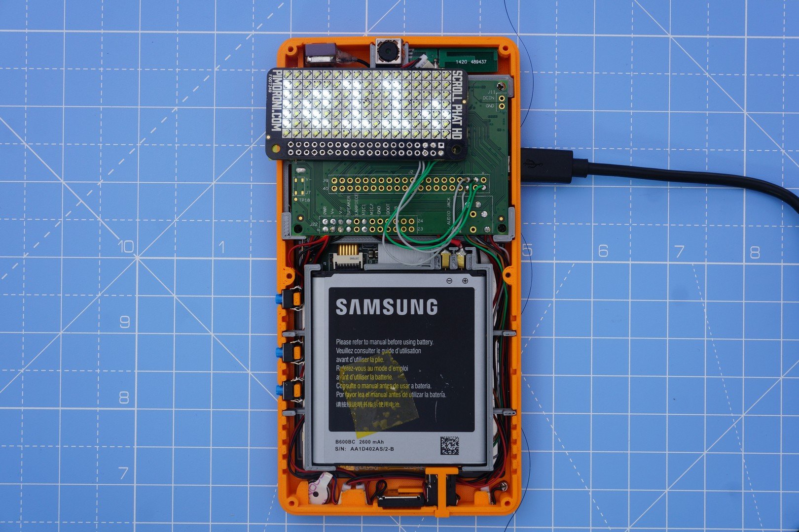
The expansion board (to which the pHAT is connected) supplies power to the pHAT, even when the phone is in sleep mode. I can send the device to sleep by disconnecting the USB cable, and pressing the power button (just like any Android device). The end result - the name animation keeps playing, even when the phone goes to sleep (note the screen is off). Mission accomplished?
![]()
Not quite. We need to get this scheme to work in Android, natively. We wouldn’t want to run a whole lot of other things (Linux userspace libraries, python,…) just to show a name on a badge – would we?
Android includes a large amount of software running over the Linux kernel. Android has an interesting security model that makes it close to impossible to access platform hardware directly. This makes sense – consumer hardware rarely has any pins available for usage. Typically, hardware access in Android happens through well-defined APIs. Most folks don’t add new hardware to Android – this generally requires the hardware to have some sort of mass market appeal/use case. That won’t work for us.
To make it easier for “hacks” like ours (and explaining stuff easily), we have disabled SELinux on our Android build. If we didn’t do that, we’d have to write at-least an additional layer of software to manage access to hardware.
An Android-ish solution would generally configure the badge from an application written in Java (using the Android APIs). There is no API to access I2C, so we’ll have to use C/C++ code to do that – and call that code using JNI. All hardware access in Android apps works more or less this way – but generally through an intermediary service (e.g. Camera). We follow the KISS principle, and because this badge is not for the world to use, we can directly communicate with the I2C device.
The I2C interface on KiteBoard is available as /dev/i2c-1, same as Raspberry Pi – to ensure that various pieces of software can run without modification. Luckily, the Linux kernel provides a userspace API - so we don't need to write messy kernel drivers for simple tasks. Using the userspace API, we can talk to the pHAT & get everything to work. It is time now to port the Pimoroni library (with our changes) to C/C++. I wrote a small C++ wrapper to make a decent library, plus a test program to check the display. (These files are in minchu-v01.zip - see directory android-source/kite/pimoroni-scroll-phat-hd after extracting the zip.)
I can build the code inside the device’s Android source tree; it could also be built with the NDK. The build inside the Android source tree requires a few steps:
$ cd <ANDROID_SOURCE_ROOT>
$ source build/envsetup.sh
$ lunch kite-userdebug
$ cd kite/pimoroni-scroll-phat-hd
$ mm
The “mm” command builds the targets inside the current directory. The executable binary is generated in $ANDROID_SOURCE_ROOT/out/target/product/kite/system/bin/test_test_lcd_gfx.
All the Android userspace resides in the “system” partition. This is the “ROM” – mostly mounted as read-only in consumer phones. To run our code, it is easiest to push the executable there. We need to mount the system partition in read-write mode & copy the file to the partition. Let's do that with adb:
$ adb root
$ adb remount
$ adb push out/target/product/kite/system/bin/test_lcd_gfx /system/bin
$ adb shell test_lcd_gfx
On Android, /system/bin is part of PATH – so the executable can be used from the command line without explicitly mentioning it's path. The port is good - so I can now see my name on the badge. The name keeps animating even after the program exits. So far, so good.
Now that the underlying functionality has been implemented, we need to make this accessible from Android – Java code. To call the native code from Java, we need to implement a JNI (Java Native Interface) wrapper – a shared library that will be loaded & invoked by the Java code. Here is ScrollPHATHD.java- a class with all native methods. The class loads libphatgfx.so - which contains the implementation of all the functions... oops "methods" I should say.
package com.isquare.kite.exthw;

public class ScrollPHATHD {

    static {
        System.loadLibrary("phatgfx");
    }

    public static native boolean init();
    public static native void deinit();

    public static void flip() {show(-1);}
    public static native void show(int page);
    public static native void animate(int delaySteps);
    public static native void picture_mode();
    public static native void set_fb_size(int w, int h);
    public static native int get_fb_width();
    public static native int get_fb_height();

    public static native void scroll(int x, int y);
    public static native void scroll_to(int x, int y);
    public static native void wrap(boolean x_wrap, boolean y_wrap);

    public static native void set_pixel(int x, int y, float brightness);
    public static native void fill(float brightness, int x, int y, int w, int h);
    public static native void clear();
    public static native void draw_char(int x, int y, char ch, float brightness, boolean reverse_video);
    public static native void draw_string(String msg, int x, int y, float brightness, boolean horizontal, boolean reverse_video);
};
With that done, we now need a standard Android application to program the badge… I want the phone to work in “badge” mode when it is in sleep. Android applications can get notifications of important activities – by implementing what’s known as a “BroadcastReceiver”. Android has “Intent”s for various events – including ACTION_SCREEN_OFF, which you probably guessed is fired just before the screen goes off. We hook on to this screen off event, and configure the Scroll pHAT HD in animation mode. After we finish, the device goes to sleep – with the animation running. Sweet!
However, the story isn’t complete yet. We are violating a fundamental law of nature here… everything that turns ON must turn OFF, eventually – else the battery will drain! We can fix that by stopping the animation when the screen turns ON. Like the screen off, Android defines a screen on event as well, ACTION_SCREEN_ON. When we receive this, we turn off the screen. Done. Here’s the code:
 private class ScreenReciver extends BroadcastReceiver {
        @Override
        public void onReceive(Context context, Intent intent) {
            String action = intent.getAction();
            if(action.equals(Intent.ACTION_SCREEN_OFF)) {
                ScrollPHATHD.init();
                ScrollPHATHD.draw_string("Shree Kumar", 0,1,0.01f,true,false);
                ScrollPHATHD.scroll_to(0,0);
                for(int i=0;i<8;i++) {
                    ScrollPHATHD.show(i);
                    ScrollPHATHD.scroll(4, 0);
                }
                ScrollPHATHD.animate(60);
            }
            if(action.equals(Intent.ACTION_SCREEN_ON)) {
                ScrollPHATHD.init();
                ScrollPHATHD.picture_mode();
                ScrollPHATHD.set_fb_size(17,7);
                ScrollPHATHD.clear();
                ScrollPHATHD.flip();
            }
        }
    }
You’ll need to compile & run the "phat" application to see it working. Use Android studio for the same. Next, let’s modify the case & include the pHAT inside it.
The pHAT is connected to the expansion board with four wires. The PCB and the components are about 4 mm thick. The completed case can’t add much thickness, if we want to take it around. in our pockets We can achieve minimum thickness, if the pHAT sits right above the expansion board.
To modify the rear cover, we will use FreeCAD, version 0.16. This open source application makes it possible to do the design in an easy-to-use user interface. FreeCAD is parametric - meaning we can measure the physical dimensions of the pHAT and fit it in. The parametric nature allows easy changes - simplifying trial & error. Something too tight? Just change the dimensions a bit by tweaking a number – no need to redo the entire design.
This post is too small to give a tutorial on FreeCAD; I will cover the important steps. The model created below is available in minchu-v01.zip, as "freecad/minchu.FCStd". This freecad model file includes measured dimensions in a spreadsheet - these dimensions are referenced to create the actual shapes.
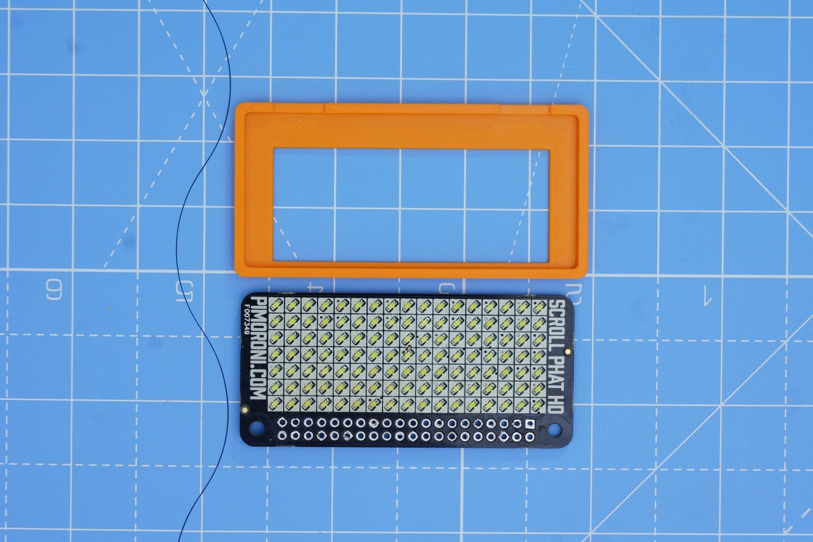
Let’s begin by designing a simple “holder” that fits the Scroll pHAT HD. The Scroll pHAT HD can be inserted inside this holder, with the LEDs visible. Let’s bevel the sides of the holder.
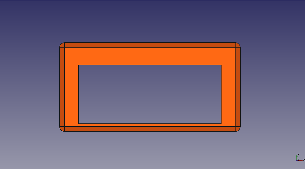
On the bottom side of the holder, there is a small cut in the plastic to help route the wires.
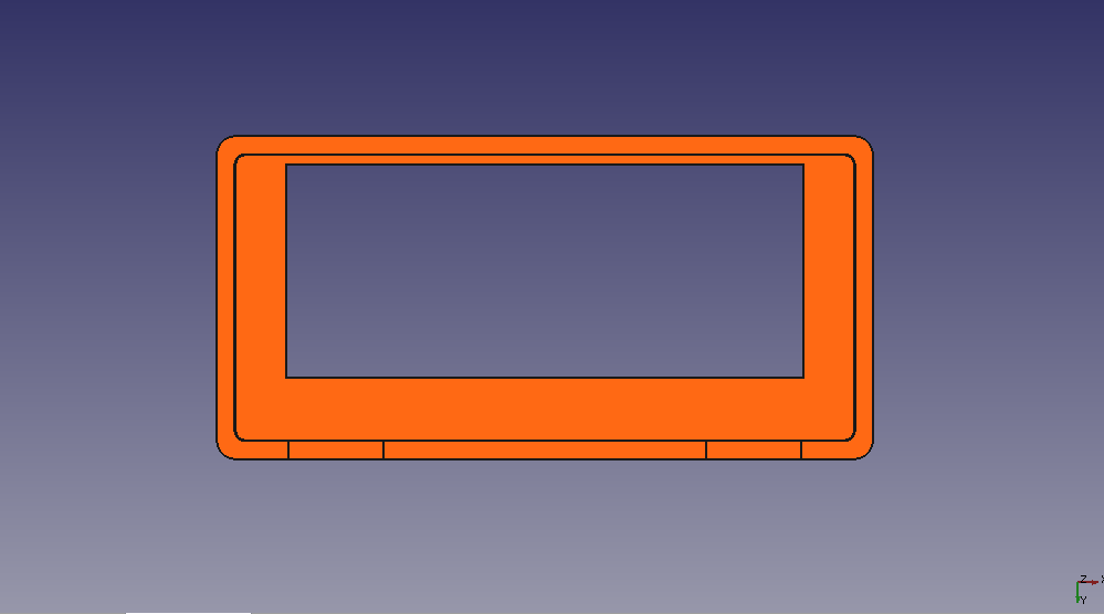
The complete part looks like this:
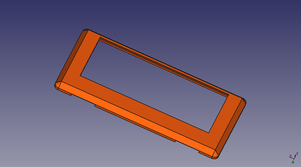
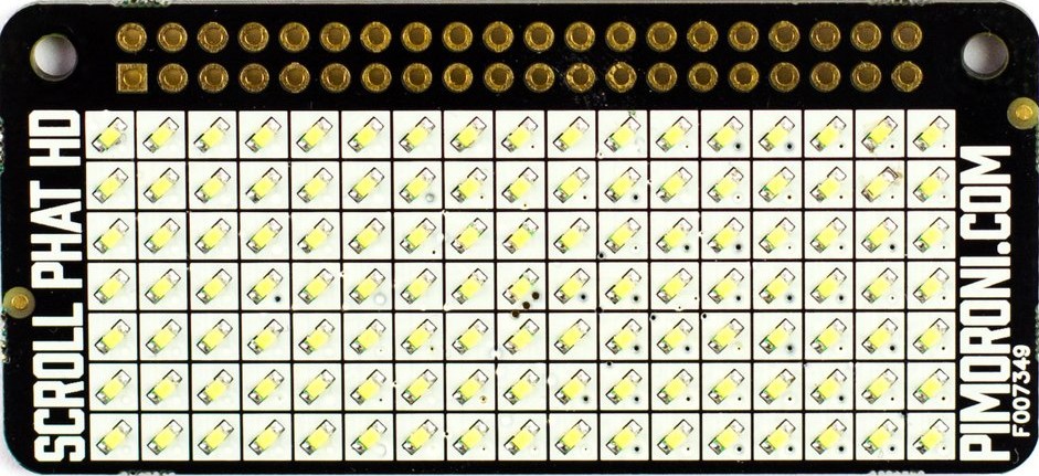
To get some idea of how things might turn out, we'll use an image of the top side of the Scroll pHAT HD:
Keeping that image in the same space as our design gives us:
This last exercise gave me a lot of confidence - if the cut matches the picture, then the print must come right... After half an hour of printing, I get the part:
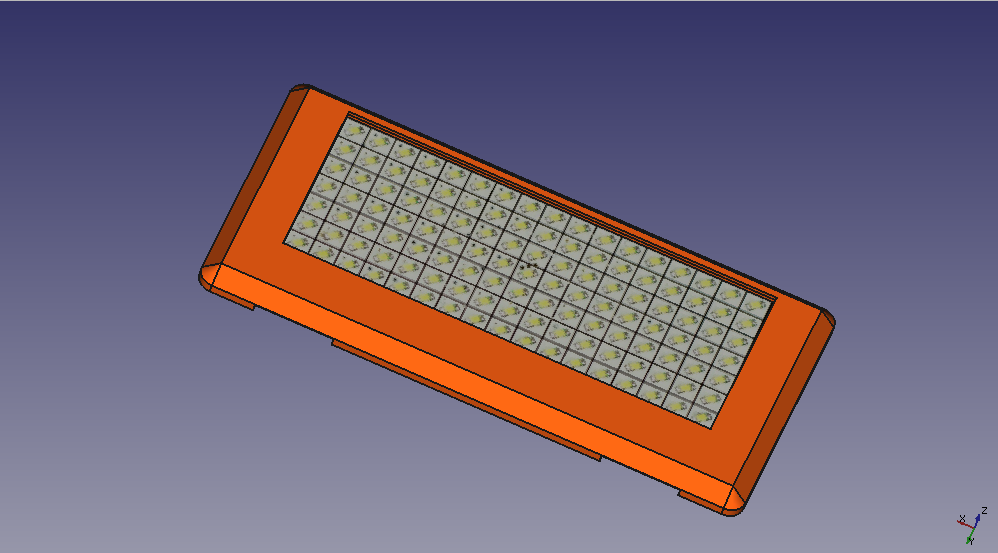
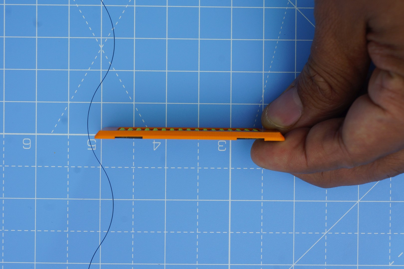
Lets put the pHAT in the cover – fits nicely! I used a tolerance of 0.1mm – which seems to give me a satisfying fit.
Let’s take a side view
Let’s place this over our open phone to see how best we can put everything together.
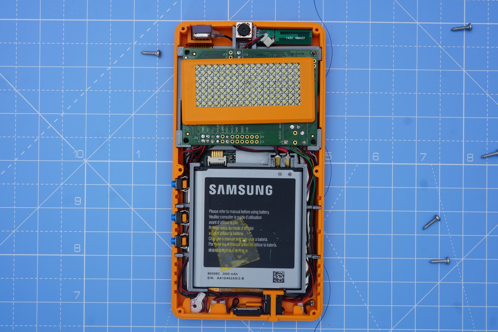
I figured this will work best. With the phone in my shirt pocket, if I want my name to be visible, then I want to have the pHAT as close to the rear camera as possible.
To accommodate this holder, I need to cut a negative of this into the holder. That’s a simple Boolean operation on two solids in FreeCAD. Picture below shows the modified rear cover, after the Boolean operation:
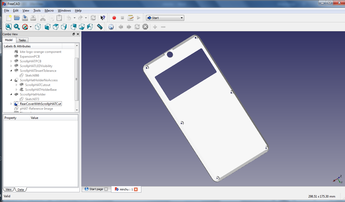
When the holder sits in the slot, the pHAT PCB will touch the expansion board, more or less. This can make a reasonable assembly. (with the phat cover visible)
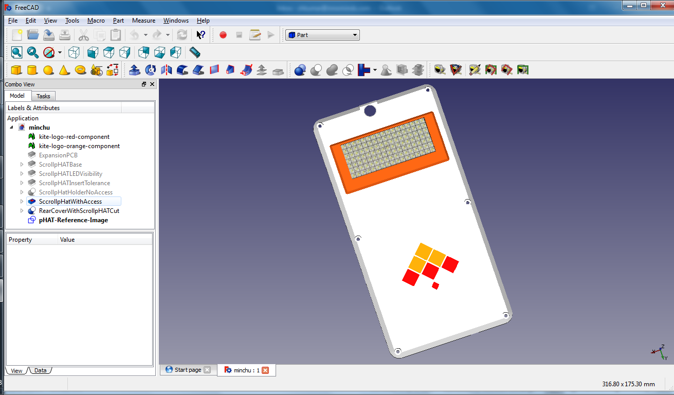
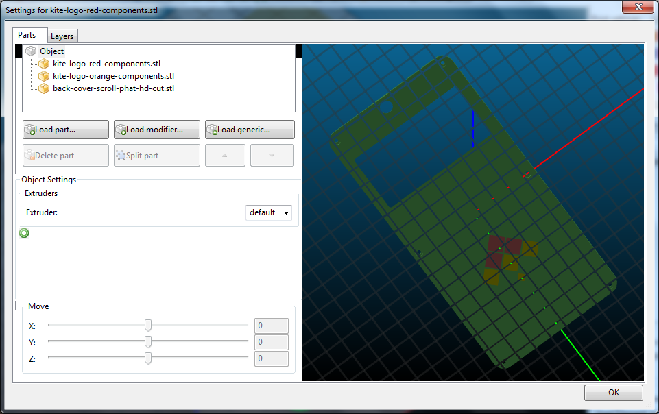
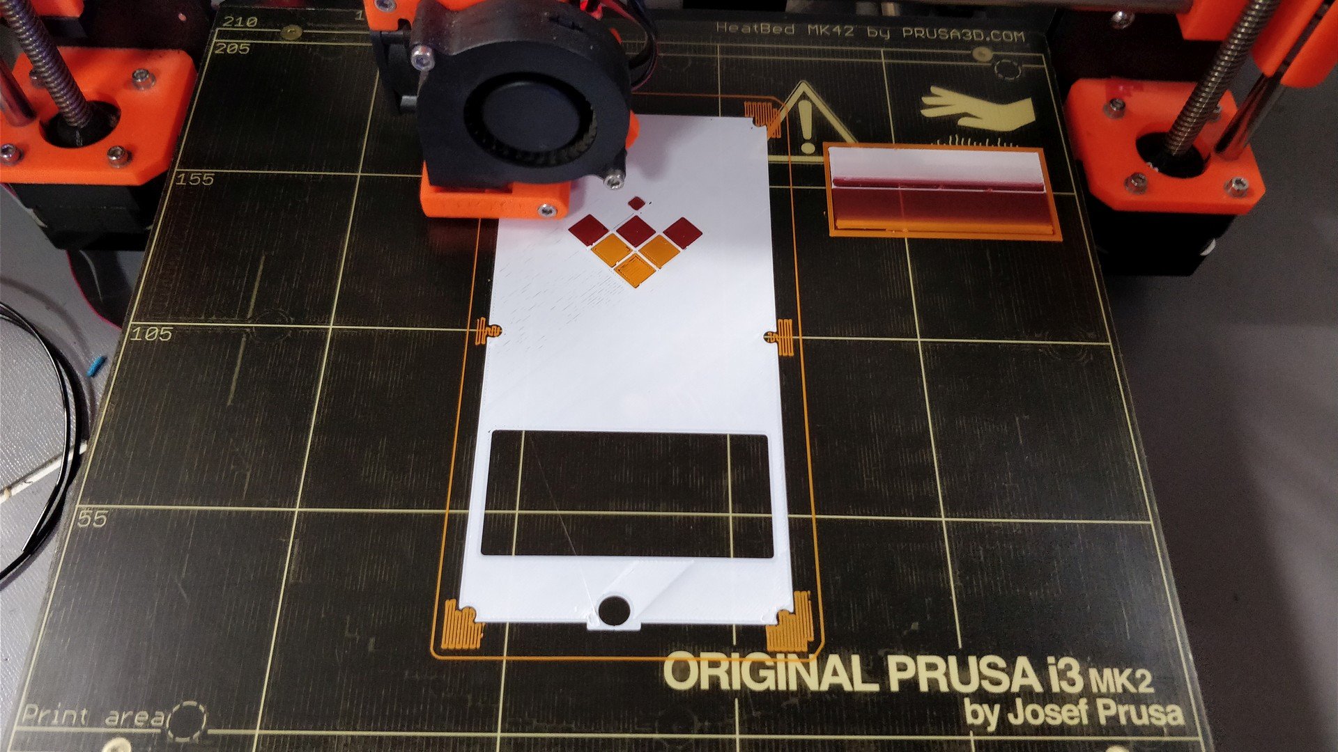
We can now print the rear cover. I have a Prusa i3 MK2 printer, with the Multimaterial printing capability – with the ability to print up-to 4 colors. To spice things up, I have included the Kite logo (orange & red parts) – hope you noticed it in the last picture. I use Slic3r for slicing the model. Each part is assigned a different extruder – 1 for orange logo piece, 3 for red logo piece, and 4 for back cover (white).
The first layer of the sliced model, for reference:
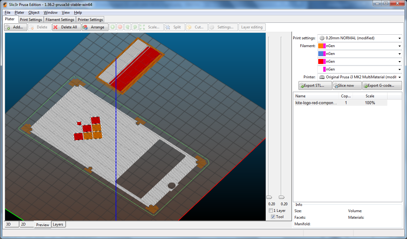
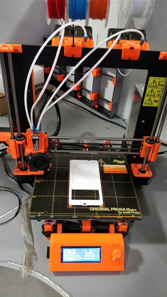
Everything looks fine, so I export the gcode to an SD card, and start the print. The first layer went reasonably well – that’s the important part with most 3D prints!
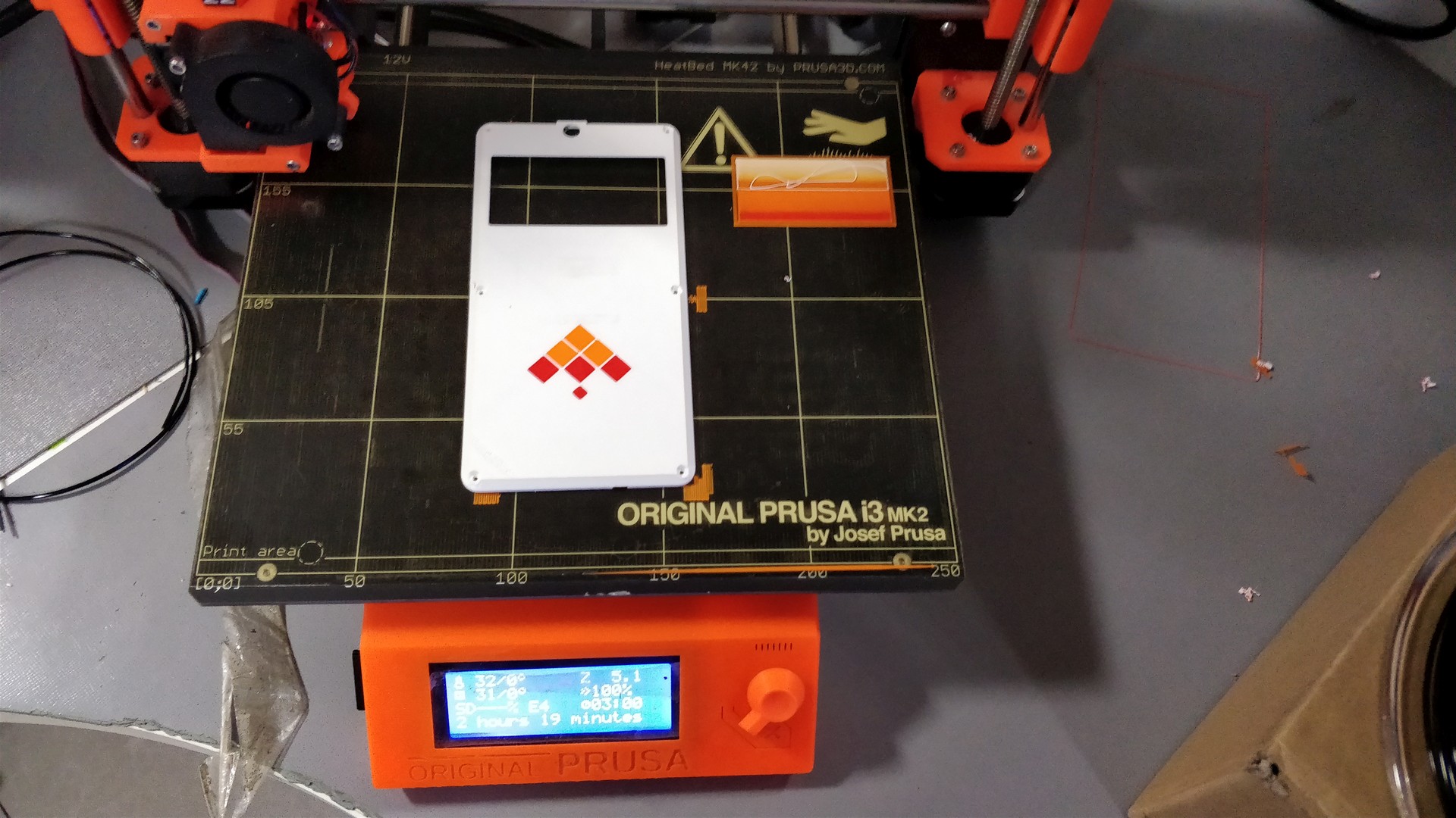
All's well that begins, and ends well. After 2 hours, 19 minutes, here's the result.
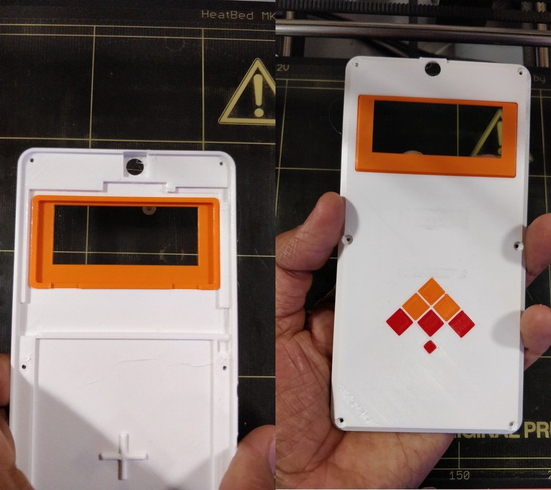
Cleaned up a bit of the support material on the screw holes. A little visual detailing can help hide all the flaws beautifully…
Time now to see if the pHAT cover will fit the modified rear cover or not. Thanks to our meticulous approach – it seems to fit well!
Great! Now, it is time to assemble the complete device. Reach out for the screwdriver to finish the masterpiece… I maybe going a bit over the top here, but let’s just say that I was overjoyed to see the complete thing. Look at the image below & judge for yourself!
Still here with me ? Great. It’s time now to explain what’s behind the name “Minchu”. As mentioned earlier, the word “Minchu” means “Lightning” in Kannada – my mother tongue (my actual mother tongue is a dialect of Kannada, but this level of detail should be good enough for now).
What’s lightning got to do with the name badge? The Pimoroni Scroll pHAT HD features 17x7 insanely bright LEDs; you wouldn’t want to stare at it with all LEDs running at 100% brightness. It’s about as bright a light as you can add to your phone – hence the name “Minchu”. The “dazzling” effect is best captured here… I wouldn’t stare at the light – if I were you!
Android is an open source project. Andriod ROMs have long put this to great use. Many features implemented in popular ROMs have found their way back into AOSP. Consumer phones don’t allow you to add hardware to them – so the amount of customization possible is limited. Kite gives you the awesome ability to add your own hardware –that alone opens-up opportunity for makers to solve various problems that will never be addressed by consumer phones... Let’s get back to the torch and show you how to modify Android.
We can use this LED panel as a bright torch. Android has this “Torch” widget in QuickSettings – accessible when you pull down the statusbar on the screen. Wouldn’t it be cool if we could use this to turn ON our LED panel? Of course, glad you asked.
Let’s hack into the “SystemUI” component in the Android framework. We will implement a QuickSettings “Tile” for the pHAT based torch. As a simple implementation, this “Tile” fires an “intent” when the torch state requires change (ON/OFF). In response to the intent, our Android application can turn all the LEDs ON and OFF. The source code is too long to reproduce here – please refer PHATFlashlightTile.java for details. We can then tap into the flashlight action, and use this new tile implementation (instead of the default "FlashlightTile") :
--- a/frameworks/base/packages/SystemUI/src/com/android/systemui/statusbar/phone/QSTileHost.java
+++ b/frameworks/base/packages/SystemUI/src/com/android/systemui/statusbar/phone/QSTileHost.java
@@ -43,6 +43,7 @@ import com.android.systemui.qs.tiles.ColorInversionTile;
 import com.android.systemui.qs.tiles.DataTile;
 import com.android.systemui.qs.tiles.DdsTile;
 import com.android.systemui.qs.tiles.FlashlightTile;
+import com.android.systemui.qs.tiles.PHATFlashlightTile;
 import com.android.systemui.qs.tiles.HotspotTile;
 import com.android.systemui.qs.tiles.IntentTile;
 import com.android.systemui.qs.tiles.LocationTile;
@@ -274,6 +275,7 @@ public class QSTileHost implements QSTile.Host {
     }

     private QSTile<?> createTile(String tileSpec) {
         if (tileSpec.equals("wifi")) return new WifiTile(this);
         else if (tileSpec.equals("bt")) return new BluetoothTile(this);
         else if (tileSpec.equals("inversion")) return new ColorInversionTile(this);
@@ -281,7 +283,7 @@ public class QSTileHost implements QSTile.Host {
         else if (tileSpec.equals("airplane")) return new AirplaneModeTile(this);
         else if (tileSpec.equals("rotation")) return new RotationLockTile(this);
-        else if (tileSpec.equals("flashlight")) return new FlashlightTile(this);
+        else if (tileSpec.equals("flashlight")) return new PHATFlashlightTile(this);
         else if (tileSpec.equals("location")) return new LocationTile(this);
         else if (tileSpec.equals("cast")) return new CastTile(this);
         else if (tileSpec.equals("hotspot")) return new HotspotTile(this);
After making these changes, we need to recompile Android, and flash the "system" partition (pro devs can use some shortcuts too – but let’s keep it simple for now).
KiteBoard is Android based - you can use fastboot to flash the system partition, just like you would with your phone:
$ cd <ANDROID_SOURCE_ROOT>
$ source build/envsetup.sh
$ lunch kite-userdebug
$ make -j8 # Build
$ adb reboot bootloader
$ fastboot flash system out/target/product/kite/system.img
$ fastboot reboot
After the phone boots, run the phat demo app. Then use the flashlight icon on the main screen to see your changes in action:
That’s it – we are done for now. The flashlight example is a simple, but useful example. With our Raspberry Pi compatibility, you can easily add various commonly available sensors to the phone. Not only will you be able to monitor the environment, but you could potentially implement entirely new ways of interacting with your favorite device.
What sensors would you want to add to your phone - and how would they impact Android? Please let me know in the comments below! Thanks for reading.
Leave a comment here