
50 mm x 70 mm x 5 mm (without connectors & switches)
50 mm x 70 mm x 8 mm (with connectors & switches)
Qualcomm MSM8916
Quad Core 64 bit ARM Cortex A53 @ 1.2 GHz
Integrated Modem with Cat 4 LTE support, 3G/2G fallbacks. Dual SIM support (DSDS). Supports voice, data & SMS.
LTE Bands
1,2,4,5,8,13,17 (North America)
1,2,3,4,5,7,8,20 (Europe hardware)
3G
Bands 1, 2, 4, 5, 8
GSM
800, 900, 1800, 1900 MHz
Android L (5.1.1)
1 GB LPDDR3 533 MHz (upgradable to 2GB)
16 GB in-build storage (eMMC)
Micro SD Card, SD 3.0 (UHS-I)
Adreno 306
WiFi b/g/n, BT 4.1, BT LE 4.0. User selectable Bluetooth power mode (Class 1/Class 2)
Qualcomm iZat Gen 8C with support for GPS/GLONASS/Beidou,AGPS support
Speaker (2W, 8 Ohm), Primary+Secondary Mic, Earpiece, I2S
9 axis accelerometer, ecompass, gyroscope
DC, LiPoly Battery, USB
3.7/3.8V LiPoly Batteries
Integrated high current (2A) charger for LiPoly battery supporting Qualcomm QuickCharge 2.0
4 lane MIPI CSI (rear) camera supporting upto 13 MP camera, with Autofocus support
1 lane MIPI CSI (front) camera supporting upto 5 MP camera
4 lane MIPI DSI interface supporting a maximum resolution of 1080p @ 60Hz
Wireless Display (Miracast) upto 720p @ 30Hz
Single USB 2.0 OTG port
15 GPIOs (9 with platform wake-up capability)
Multiplexed UART (upto 2), SPI (upto 4), I2C (Upto 4) interfaces. Unused pins can be used as additional GPIOs
Single RGB LED
FM Radio Receiver
Power (Button)
Volume Up & Down (Pads)
Vibrator Motor (Pads)
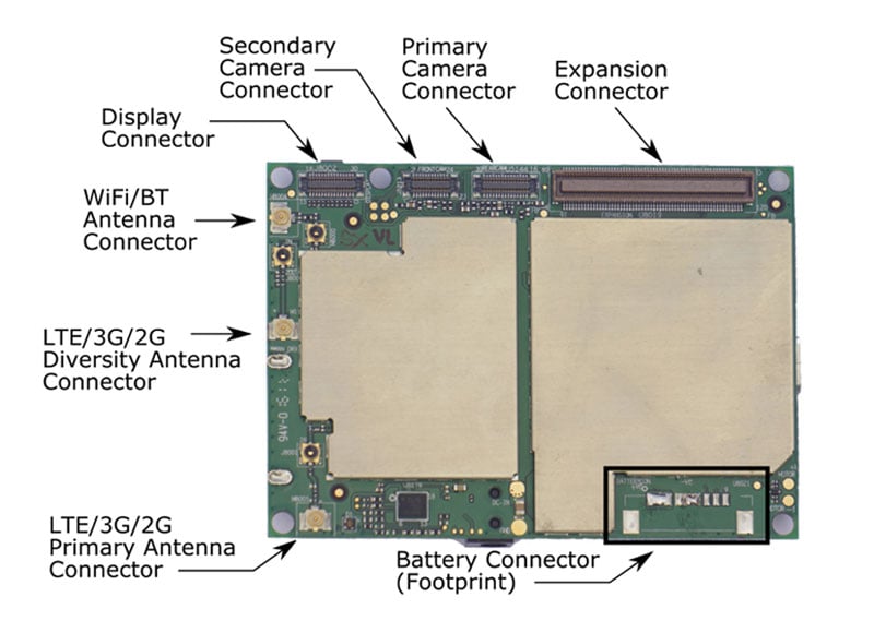
| CONNECTOR | CONNECTOR TYPE | SIGNALS | OPTIONAL/INCLUDED |
|---|---|---|---|
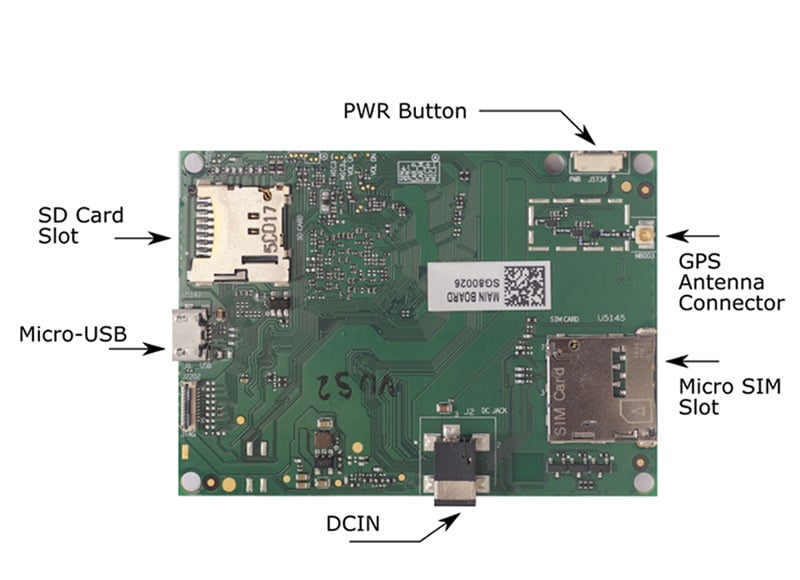
| USB | USB Micro B | USB 2.0 | Optional |
| DC Input | DC Power, GND | Optional | |
| SIM | Micro SIM | SIM 1 | Optional |
| SD | Micro SD | SD Card | Optional |
| Expansion | 120 pin board to board connector, 4mm stacking height |
GPIOs,UART/I2C/SPI, system power, SD, SIM1 & 2, USB, Audio signals, Buttons |
Included |
| Primary Camera | 30 pin FPC | 4 lane MIPI CSI, autofocus, power, CCI |
Included |
| Secondary Camera | 24 pin FPC | 1 lane MIPI CSI, power, CCI |
Included |
| Display | 30 pin FPC | 4 lane MIPI DSI, I2C, I2S, PWM, Power, Extra GPIOs |
Included |
| LTE Primary Antenna Connector | IPX | Included | |
| LTE Diversity Antenna Connector | IPX | Included | |
| WiFi/BT Antenna Connector | IPX | Included | |
| GPS Antenna Connector | IPX | Included | |
| Battery | Power, GND, Thermal sense, I2C | Optional |
The Display connector supports MIPI displays. The display connectors includes an I2C interface, which can be used to directly interface a touch panel. A backlight PWM pin, power & GPIO signals are provided to make it possible to directly interface common MIPI displays panels with integrated touch. Interfacing LVDS/RGB/HDMI displays requires usage of a bridge chip and circuitry to convert the signals. I2S signals are also routed to the display connector – this can be used to implement HDMI audio if required.
USB Micro B, DC Input, MicroSIM, and MicroSD connectors are mounted in development boards. They are, however, optional in production boards. The signals on these connectors are routed to the expansion connector as well – this allows placement of the connectors at an appropriate place, as required in the target application.
50 mm x 70 mm x 5 mm (without connectors & switches)
50 mm x 70 mm x 8 mm (with connectors & switches)
Qualcomm MSM8916
Quad Core 64 bit ARM Cortex A53 @ 1.2 GHz
Integrated Modem with Cat 4 LTE support, 3G/2G fallbacks. Dual SIM support (DSDS). Supports voice, data & SMS.
LTE Bands
1,2,4,5,8,13,17 (North America)
1,2,3,4,5,7,8,20 (Europe hardware)
3G
Bands 1, 2, 4, 5, 8
GSM
800, 900, 1800, 1900 MHz
Android L (5.1.1)
1 GB LPDDR3 533 MHz (upgradable to 2GB)
16 GB in-build storage (eMMC)
Micro SD Card, SD 3.0 (UHS-I)
Adreno 306
WiFi b/g/n, BT 4.1, BT LE 4.0. User selectable Bluetooth power mode (Class 1/Class 2)
Qualcomm iZat Gen 8C with support for GPS/GLONASS/Beidou,AGPS support
Speaker (2W, 8 Ohm), Primary+Secondary Mic, Earpiece, I2S
9 axis accelerometer, ecompass, gyroscope
DC, LiPoly Battery, USB
3.7/3.8V LiPoly Batteries
Integrated high current (2A) charger for LiPoly battery supporting Qualcomm QuickCharge 2.0
4 lane MIPI CSI (rear) camera supporting upto 13 MP camera, with Autofocus support
1 lane MIPI CSI (front) camera supporting upto 5 MP camera
4 lane MIPI DSI interface supporting a maximum resolution of 1080p @ 60Hz
Wireless Display (Miracast) upto 720p @ 30Hz
Single USB 2.0 OTG port
15 GPIOs (9 with platform wake-up capability)
Multiplexed UART (upto 2), SPI (upto 4), I2C (Upto 4) interfaces. Unused pins can be used as additional GPIOs
Single RGB LED
FM Radio Receiver
Power (Button)
Volume Up & Down (Pads)
Vibrator Motor (Pads)
| CONNECTOR | CONNECTOR TYPE | SIGNALS | OPTIONAL/INCLUDED |
|---|---|---|---|
| USB | USB Micro B | USB 2.0 | Optional |
| DC Input | DC Power, GND | Optional | |
| SIM | Micro SIM | SIM 1 | Optional |
| SD | Micro SD | SD Card | Optional |
| Expansion | 120 pin board to board connector, 4mm stacking height |
GPIOs,UART/I2C/SPI, system power, SD, SIM1 & 2, USB, Audio signals, Buttons |
Included |
| Primary Camera | 30 pin FPC | 4 lane MIPI CSI, autofocus, power, CCI |
Included |
| Secondary Camera | 24 pin FPC | 1 lane MIPI CSI, power, CCI |
Included |
| Display | 30 pin FPC | 4 lane MIPI DSI, I2C, I2S, PWM, Power, Extra GPIOs |
Included |
| LTE Primary Antenna Connector | IPX | Included | |
| LTE Diversity Antenna Connector | IPX | Included | |
| WiFi/BT Antenna Connector | IPX | Included | |
| GPS Antenna Connector | IPX | Included | |
| Battery | Power, GND, Thermal sense, I2C | Optional |
The Display connector supports MIPI displays. The display connectors includes an I2C interface, which can be used to directly interface a touch panel. A backlight PWM pin, power & GPIO signals are provided to make it possible to directly interface common MIPI displays panels with integrated touch. Interfacing LVDS/RGB/HDMI displays requires usage of a bridge chip and circuitry to convert the signals. I2S signals are also routed to the display connector – this can be used to implement HDMI audio if required.
USB Micro B, DC Input, MicroSIM, and MicroSD connectors are mounted in development boards. They are, however, optional in production boards. The signals on these connectors are routed to the expansion connector as well – this allows placement of the connectors at an appropriate place, as required in the target application.